January 25, 2018
By: Chett Norton, C.E.T. and Sylvia Flegg
As a manufacturer of gasket material, a common question we are often asked is, “How can you cut this”? It’s a great question that can yield several options based on the knowledge of our experienced gasket engineers to help meet your needs quickly and economically.
When it comes to soft gaskets, there are three main cutting methods with each providing its own pro’s and con’s depending on the gasket requirements. The main considerations for each method are time, quantity, tolerance requirements, material scrap/yield and the quality of cut.
Gasket Cutting Processes
1. Manual cutting methods are very common and generally performed in plants for jobs that require custom gaskets to be cut in the field. The material can be cut with a utility knife, scissors or shears, or even by a battery operated device. The dimensional tolerance of hand cut gaskets is based on the person cutting the gaskets, however, realistically the tolerance on most hand cut gaskets would be greater than +/- 3.2mm (1/8”). Additionally, with hand cut gaskets, there is usually more than one scribe or cut mark, which can potentially lead to jagged edges or nicks in the gasket, thus creating a weak point. Manual cutting is somewhat slow and tedious, and tends to result in a higher yield of gasket scrap or waste.

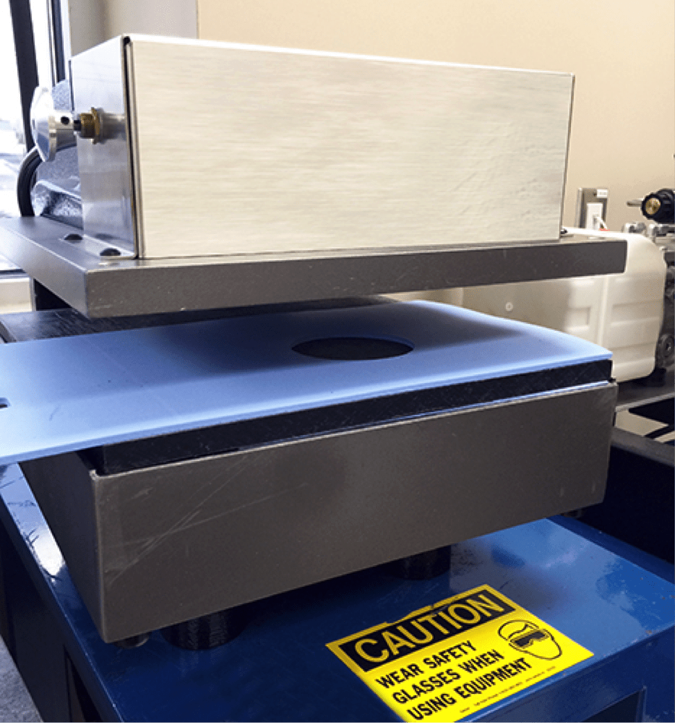
2. A Clicker press is another method that is commonly used in higher production runs. A rolled steel die is made up and then the die is placed on the material and pressed into it by a pneumatic press. The tolerance of the gasket is much higher than manually cutting and the material yield is much better. The process is still done manually, however, the yield of material is based on the user/operator. The process is economical for larger gasket quantities because a die still needs to be made for each size and there is some maintenance involved in sharpening and maintaining the dies. Die cutting is not recommended for larger OD gaskets, or custom sizes that required small quantities.
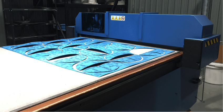
3. CNC digital cutters utilize a 3-axis cutting head that have either an oscillating head or drag knife that cuts the material. Gasket dimensions are converted to CAD drawing file(s) and then uploaded into the machine to be cut. The big benefits to using these types of cutters are the speed, high level of accuracy and material savings due to being able to nest all the gaskets together for the optimal yield. Additionally, for custom size gaskets there is no die or tooling required just a CAD drawing to upload. Literally the operator can put the material on the table, nest the gaskets desired to cut and hit start and walk away.
We have many custom fabrication capabilities and we’ve seen success with all of these in different materials on our product line. If you don’t produce your own gasket material, one of the most important things you can do is ask your gasket manufacturer how they would recommend you cut the material. It sure beats wasting time and precious material!
Happy Cutting!
Custom Cut Gaskets, made to order. Simply send us your CAD file, detailed drawing or gasket photo and we can manufacture your fully customized gasket design. The end result is a quality gasket, made to your specifications, priced right and shipped in days. Contact Us Now!
SELECTING PROPER GASKETS FOR WATER TREATMENT FACILITIES INVOLVES MANY CONSIDERATIONS
By Chett Norton, C.E.T
The importance of plant operators and operations in water treatment facilities selecting the right gaskets cannot be overstated. Unfortunately, they are often the last thing that anyone thinks about, and are in most cases considered a commodity item. However, most operators say that it is gaskets that can cause the most “pain” on a day-today basis. This means that selecting the right ones is important for process safety, environmental protection, service life, and maintenance and inventory costs.
The National Sanitation Foundation (NSF) has created standards that are intended directly for drinking water and systems that treat and deliver it. NSF/ ANSI 61 standard is based on the health effects of drinking water components.
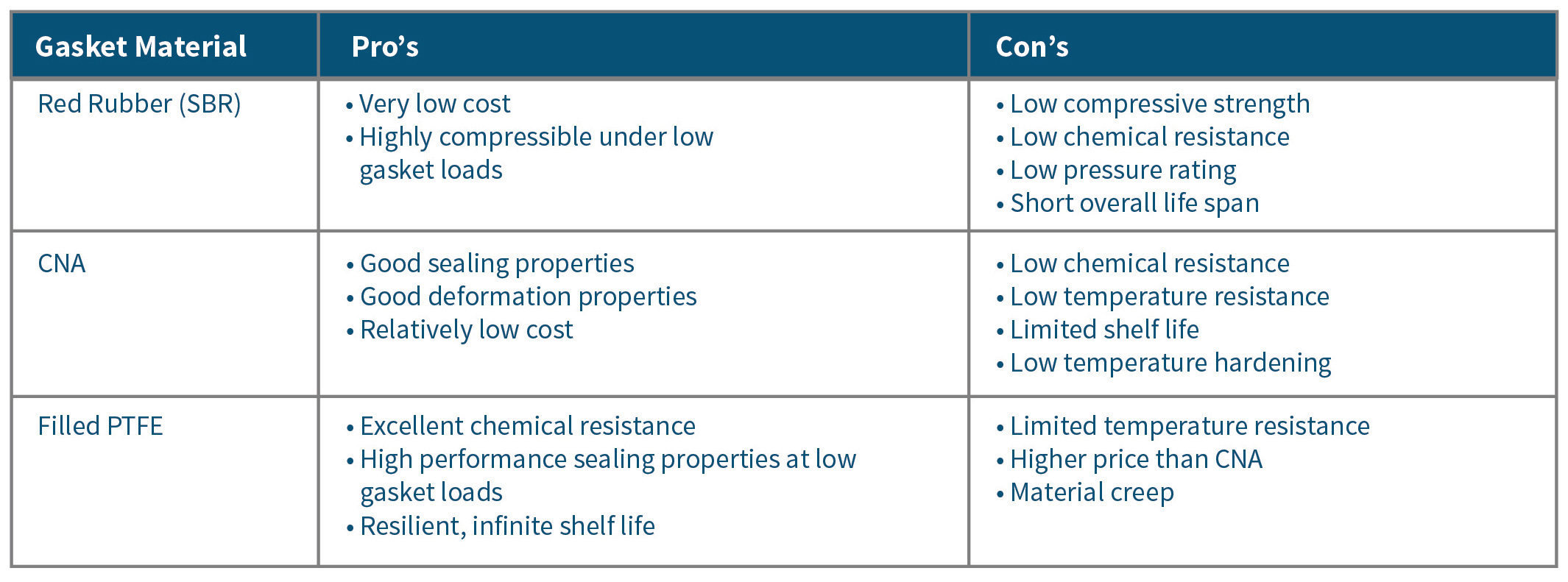
Unfortunately, municipal facilities do not always use NSF 61 approved gasket material. Red rubber, styrene butadiene rubber (SBR), is continually used for potable water applications. But, it is not an ideal gasket material because it is a pure elastomer which naturally degrades over time, because of natural environmental conditions. Red rubber also has a very low compressive strength, generally in the range of 800 psi – 1200 psi, which can result in the material crushing if these values are exceeded.
In most flange pipe connections, the amount of torque applied to the bolting to achieve a minimum bolt stretch of 40% may exceed these values. Failing to stretch the flange bolts to this minimum yield can be problematic because the bolting material is not within its elastic region, and cannot create a “spring like” clamping effect on the flanges. This can result in a leak, or perhaps a blow-out failure.
The chemical resistance of SBR is relatively low against common water treatment chemicals like sodium hypochlorite, caustics, chloramine and others. These chemicals can aggressively attack the red rubber, resulting in a rapidly degraded or deteriorated gasket. When the gasket is chemically attacked, it is susceptible to leaks, failures or perhaps even a gasket blow-out which can seriously harm plant personnel if they are sprayed with these chemicals.
For general plant services that process non-potable water, steam and various forms of waste products, compressed non-asbestos (CNA) gasket material is a good choice because of its good sealing characteristics, ease of cutting and relatively low cost.
CNA gasket material has three main components: fibre (15% – 35%), binder (10% – 20%), filler (50% – 70%). Additionally, there is a small percentage of vulcanizing chemicals which are usually solvent based and used to cure the rubber based binders during manufacturing. Fibre is added to the CNA gasket material to provide increased mechanical properties like tensile and compression, and can include aramid, cellulose, ceramic and glass. The binder is usually composed of an elastomer, namely nitrile, styrene butadiene rubber, or even ethylene propylene diene monomer rubber, which keeps the sheet bound and gives the gasket material added flexibility.
Fillers such as silica, mica, clay or even powdered graphite can be added to help control creep and reduce cold flow. Additionally, using fillers helps reduce the overall cost of the sheet because it consists of 50% – 70% of the total material. When selecting a CNA gasket material for potable water, the user should make sure they use a NSF 61 verified material to ensure that they are not contaminating the water source. Because CNA gasket material contains a rubber component, the material still does have a shelf life. Over time, the rubber will start to break down and deteriorate, based on exposure to environmental conditions.
Due to the rubber component of this type of gasket material, it is not recommended to seal applications that involve acids, or caustics which are used in pH control prior to the clarifying stages or even disinfection chemicals such as sodium hypochlorite (NaClO), 12% solution.
Even polymer-based chemicals used in wastewater treatment, including flocculants, coagulants and defoamers, can cause deterioration in rubber-based gasket materials. Therefore, it is very important to test the chemical resistance of the gasket material used with each chemical and to measure the concentration.
For critical service and chemical applications, filled polytetrafluoroethylene (PTFE) gasket material is an excellent choice because of its in-service longevity, chemical resistance and high sealability.
PTFE has an infinite shelf life; therefore, it does not break down during exposure to environmental conditions. This makes it a superior choice for applications that are not easily accessible or perhaps buried underground. PTFE is also inert to almost every chemical, making it a great choice for chemical applications.
Pure virgin PTFE has high creep/relaxation characteristics, so it is not a good sealing material. To help prevent material creep, gasket manufacturers use engineered filler systems that can consist of glass, barium sulfate and/or carbon.
Filled PTFE seals at a much lower gasket stress than compressed non-asbestos products. However, it can also withstand loads of up to 15,000 psi, which is more than 10 times the compressive strength of red rubber. 75 mm, 200 mm and 300 mm 150# ANSI flanges can be problematic to seal due to the low cross-sectional “bolt area” to gasket “sealing area” ratio. Full face gaskets are also difficult to seal when compared to ring gaskets, due to having two to three times more sealing area. For these applications, filled PTFE is a preferred sealing material.
Full face flanges are generally found on pumps and cast iron 125/250# piping. In many cases, you cannot generate enough gasket compression stress to create an effective seal without damaging the flanges. For these flat face flange applications, reducing the gasket area will help increase the gasket stress. When bolting up the gasket, a reduced contact area gasket made up of filled PTFE, will allow the full face skeleton design to support the entire flat face flange. It will also prevent any damage that may be caused by bending or flange rotation if a ring gasket were to be used.
The application will influence the gasket selection; however, proper gasket installation is equally important. Based on 100 gaskets analyzed and material collected from the members of the Fluid Sealing Association, up to 85% of gasket failures were due to faulty user installation. Sixty-eight percent of the gaskets failed due to under compression, while 14% failed due to over compression.
It should be noted that both under and over compression of the gasket can be prevented if installers use a proper tightening method, recommended torque value and a calibrated torque wrench or other tightening device. For proper gasket installation methods, users can reference the ASME PCC-1 post construction guideline for pressure boundary bolted flange joint assembly. Gasket manufacturers provide recommended torque values and installation procedures.
Click here to view other articles from this issue (Dec 2017).
Triangle Fluid Controls (TFC) proudly congratulates Chett Norton as the recipient of the FSA Award of Merit in recognition of his exceptional technical contributions to the Association and for his efforts to promote the mission of the FSA.
The Award of Merit is presented by the Board of Directors and the Members of the Fluid Sealing Association and was established to recognize distinguished or exceptional service to the FSA by an individual member and granted solely on merit and participation in all activities that support the FSA mission.
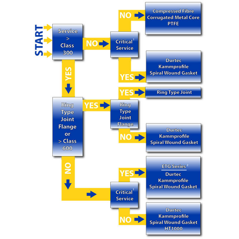
When it comes to finding the appropriate gasket material for your system, gasket selection can be one of two things: confusing or intimidating. Some are not sure where to begin, while others find the thought of dangerous leaks or costly shutdowns put them on edge. To help ease the selection process pain, we have developed a few simple tools that will help with gasket selection.
The first, a simple gasket flowchart, will help narrow down which Durlon sealing product is best based on a few simple operating condition guidelines.
-
- 1. Critical service can be any factor essential to plant operation or personnel/plant safety and can include environmental compliance. Failure or disruption of any critical service could result in serious impacts such as fines, time loss and/or injuries.
- 2. Durlon Extreme Temperature Gasket Series
*Note: This information is a general guide for the selection of a suitable gasket material. Triangle Fluid Controls does not accept responsibility for the misuse of this information.
How To Select
Gasket Material
No matter the gasket application there are always 3 things that need to be verified:
-
Pressure
-
Temperature
-
Media
Pressure x Temperature
Gaskets are composed of and contain various binders, fillers, materials and metals. Each gasket type or material can have very specific pressure and temperature parameters that affect the performance of the gasket. For compressed non-asbestos and PTFE gasket materials, both temperature and pressure are critical and the result of not verifying these values could result in a leak or possibly a blowout. Generally, as the temperature increases, the material pressure rating decreases for that material. To help identify pressure and temperature limitations of a product, there are Pressure vs. Temperature charts (also known as P x T charts) that will essentially give you a “Yes” or “No” answer when selecting material. When the intersecting point of both the pressure and temperature of your application are inside the material boundary (green area below), it lets you know that material is safe to use for your application.

Media
Media can be verified by simply checking out a chemical resistance chart and verifying whether the material is chemically compatible. Unfortunately, most chemical compatibility charts are based on standard concentrations at room temperature, so you may find some ratings as ‘C’ for caution or ‘N/A’ for unknown. In these cases, contact TFC engineering for further information.
Here’s an easy tool we developed to help identify chemically compatibility (resistance). Click on the image to use the tool.

You should always feel confident that you are using the correct material for installation, but if you are still unsure, I highly recommend speaking with a trained applications engineer. Contact us to learn more about gasket selection from the fluid sealing experts at TFC.
Until next time, keep the fluid between the pipes!
Why are in-line check valves so expensive?
June 8, 2017
By: Bruce Ellis and Stephanie Jouppien
As Canada’s national DFT Check Valve channel partner, we speak with many different people across many different industries in need of an in-line check valve. Once we’ve priced out a valve that fits someone’s needs with custom sizing, trim and exotic metals, it’s common for a new user to baulk at the price tag. We’re used to hearing the question, “Why are check valves so expensive?”. That is why we feel the time has come to address one of the biggest factors in a customer’s buying decision: cost. Cost is a factor that tends to make a rookie salesperson uncomfortable, and I won’t lie, check valves aren’t all inexpensive. My intention is not to have you buy the most expensive valve on our shelf today. It is to have you look past the initial, upfront costs, and instead consider your needs combined with the lifespan you would like to get out of your valve.
In any given application, valves can cost four or five times as much as a competitive product, but here are 4 things that must be considered when weighing Cost vs. Benefits:
What is your media?
Are you dealing with a fluid that is highly acidic or caustic? If so, the trim in these applications may need to be of a higher-grade alloy than the standard offerings of 304 or 316 SS (stainless steel) for chemical resistance purposes. If required, most check valve manufacturers can offer you trim and casing choices ranging from alloy 20 to titanium. However, dependent on which alloy is needed, some prices will be inherently more expensive.
Does your pump have a high cycle rate?
This is where a simplistic valve design and custom sizing become important. With fewer moving parts than swing checks and double door designs, there is less chance of parts breaking off the valve and potentially damaging other components in the system. As we have explained here proper check valve sizing is essential to ensuring they function correctly and do not prematurely wear out internal components. Building a design around your flow and pressure needs, is the key to having a worry-free valve in service.
Do you have water hammer problems?
The DFT valve design virtually eliminates this costly and damaging issue. Again, this can be handled by custom sizing your valve for the application, not the line size. Unlike a swing check, DFT silent check valves do not rely on gravity or fluid flow to close. Instead, the disc closes by the spring assist, just a short distance from where the disc must close to prevent backflow and water hammer on both sides of the valve.
What is the cost of downtime?
Ask any Production Manager this question and they cringe. Imagine stopping production in a plant of 200 employees that make $20/hour CAD for an entire 8 hour work day. That’s $32,000 CAD in lost revenue for just a single day. Or imagine stopping production in a Northern mine where underground and service miners typically start at $21.50 CAD and are onsite 12 hours a day, 7 days a week, for 2 weeks at a time. An inferior check valve installed for de-watering in this instance could fail and lead to high revenue loss from labour and downtime.
All things considered, is it really expensive to use a top-quality product? Especially one that could be in service 70+ years from now? The answer is a resounding NO. It makes sense to use a check valve that is made to or above industry standards. It is also good to note that all DFT in-line check valves are made in the USA and were designed to give years of trouble-free service. Take these examples of application success stories from DFT Inc’s website:
Problem: A chemical facility in the USA, was experiencing extreme water hammer and pressure spikes with their cycling double door check installed in a cooling tower loop pump discharge application. This caused damage to the check valves and components around them. The 10” double door valves being used at the time, had to be replaced every 6 months due to cycling.
Solution: Three – 10”, 150/300# ALC Check Valves replaced the worn double door check valves eliminating the water hammer and the valves have performed well since installation.
Installed Since: 2012
Problem: A food processor in the Midwest was requesting assistance in their wash down stations that must be sanitized using very hot water at 74°C (165°F) or higher.
Solution: The DFT® model SCV® Check Valve was used to meet safety needs and criteria.
In Service Since: The 1950’s & 60’s.
Problem: A petrochemical plant was experiencing swing check valve failures. The plant was part of an OEM turbo-expander that originally installed swing check valves. These original valves had failed quickly due to low flow and excessive cycling/pounding.
Solution: The DFT® model GLC® Check Valves were custom-sized for this application to minimize excessive cycling and chattering problems that were seen with the previously installed swing-type check valves.
Installed Since: 1999
May 4, 2017
Gasket installation seems like a simple concept:
You take a gasket, put it between two pipes, tighten the bolts and voilà…..it’s done.
Although this seems like a straightforward process, even to a seasoned veteran pipefitter, it can be tedious or downright scary if proper care is not taken during the installation process. To help with gasket installation, I have compiled a list of 6 of my favorite tools that will help even the most novice pipefitter install gaskets with ease. Before reading this list, you should already know how to install a gasket.
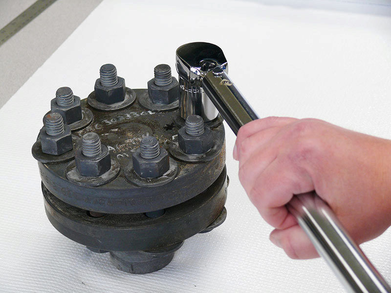
Torque Wrench
They can come in many shapes, sizes and styles ranging from the basic beam, clicker wrench or even electronic wrench. In 60% of gasket failures, the main cause of the failure is linked to under loaded gaskets. Applying the correct torque helps ensure that you are properly stretching the bolts, which in turn act like a spring pulling the flanges together, creating load on the gasket and achieving an effective seal. Torque wrenches can range in price and accuracy, however, despite the tool’s price tag, a torque wrench is only as good as it’s last calibration. So be sure to do this before putting it to use.
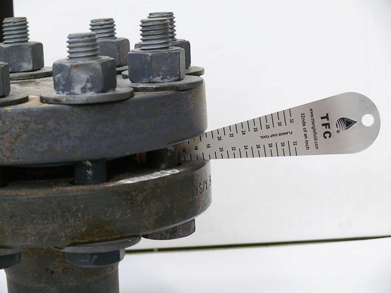
Gap Tools
These little dandies are very important in the gasket installation process. An important thing to remember is that bringing the flanges together in parallel ensures maximum contact between the flange and gasket. This transmits the most load that can be applied to the gasket, increasing the chance of success with your gasket installation. When you are tightening the bolts, it is important to measure the gap between the flanges, around the flange circumference in a minimum of 6 spots. If the gap is uneven, loosen or tighten the appropriate bolts until the gaps are within 1/32” (0.8mm). Once the flange gap spacing is evened out, you can continue with your cross star tightening pattern. The flange gap should be checked between every tightening round, paying special attention to first 2-3 passes.
Drift Pins
These hardened tapered steel pins aid in the alignment of flanges. Inserting a minimum of two drift pins into the flange bolt holes helps with two things: flange hole rotational alignment and centre line high/low alignment. After these pins have been inserted and the flanges are properly aligned, the bolts can be inserted with ease for future tightening.
Flange Spreader
Tight quarters or flanges that have very little spacing or clearance make it difficult to install a gasket and can increase installation time. Prying flanges apart with a bar or screwdriver is not a good idea, nor a safe one. Flange spreaders allow you to safely increase the gap between the flanges and give you enough room to remove the old gasket and insert a new one.
Sharpie
Perhaps one of the cheapest items on the list, but a useful one. A permanent marker such as a “Sharpie” allows you to number the bolts correctly so that you can follow a cross bolt tightening pattern during multiple rounds of tightening and not forget where you left off or which bolt is next.
This is not necessarily a physical tool, however, it can help a great deal with the installation procedure. These documents give the installer step-by-step instructions of the installation procedure in a check list format with the appropriate torque values for the installation. These sheets can also record the size, class, condition, bolting material, lubrication and installer. These installation details can be recalled at a later date and may help you will troubleshooting a problematic flange or a difficult sealing application based on previous installation history.
Hopefully you found my recommendations useful and have learned something new. If you haven’t tried any of the tools I mentioned, give them a try to compare things like ease of installation, tool usability, and installation time. Until next time, work safe, work smart and most importantly……keep the fluid between the pipes! If you would like more detailed information related to gasket installation, contact us.
1. Critical service can be any factor essential to plant operation or personnel/plant safety, and can include environmental compliance. Failure or disruption of any critical service could result in serious impacts such as fines, time loss and/or injuries.
2. Extreme Temperature Gasket Series
*See product descriptions for more information
NOTE: This selection chart is for general use only. For critical applications consult with Triangle Fluid Controls technical department. Triangle Fluid Controls does not accept responsibility for the misuse of this information.
March 2, 2017
By: Bruce Ellis and Stephanie Jouppien
You may have heard this one before but size really does matter!
When it comes to check valves or one-way valves, the properly sized valve is the best preforming valve. As simple as this logic is, check valve sizing is largely misunderstood. Check valve “sizing” refers to how much the valve’s disc opens in order to accommodate media flow through a pipe – a vital component to the system’s overall functionality. Engineers typically oversize their designs anticipating a greater demand or line capacity down the road, however, it’s usually more than is necessary and many projects are already over-specified when designed. A good place to start with check valve sizing is to ask yourself:
“What will the check valve be used for 90% of the time?”
Check valves should be specified for the current application and can be re-sized at a later date to fit future requirements.
Check Valve Chatter: It’s Trying to Tell You Something
Valve sizing is by no means a new topic. Valve manufacturers have long recognized the importance of proper sizing and how often it’s misinterpreted in the field. It’s important to point out that unlike a standard open-close valve, check valves are flow sensitive. They are designed to allow fluid, steam or gas to flow in one direction. As the flow ceases, the valve’s internal disc automatically closes [see below video animation for more info]. Let’s say a project is over specified to use 6” piping where 4” would be suitable for its current use. In this instance, a 6” valve would be needed but is not the flow rate maximum (the maximum volume of media that travels through a pipe in one minute). A regular 6” valve used in this manner would be subject to pressure loss and would not fully open, causing it to flutter against its internal stop, making chattering sounds due to unstable flow. This will significantly shorten the valve’s lifespan by causing wear on the metal internals or by causing the disc to become stuck open, possibly leading to complete valve failure. Though less common, there are instances in which valves are undersized or under-spec’d which leads to a flow restriction.
How to Calculate Valve Size
In order to properly size a check valve, you must have viscosity of material, media, pressure, temperature and flow rate (defined as: the number of US gallons of water per minute at 60°F that will flow through the valve with a pressure drop of 1 psi) to be able to customize a centre-guided check valve to the application – this involves changing the distance the disc travels from the closed to full open position. When the valve’s disc is stable and fully open or closed against the seat, no fluttering, chattering or excessive vibration will occur.
Tips & Tools for Sizing
DFT Inc. has a sizing program that uses the required information from above to calculate the required amount the valve must open to accommodate flow volume. This calculation is used to make a travel stop that is installed in the valve. The disc will be able to fully open against the stop, keeping it stable in the flow.
For further reading on check valve sizing, we recommend reading DFT’s E-Book: “Common Mistakes in Check Valve Sizing.” If you prefer a more personalized approach to sizing for a custom application, fill out this contact form and a check valve expert will follow up with you.
Proper sizing is essential and will ensure that the valve works at peak efficiency and will require less downtime, maintenance or result in a dreaded system failure. Happy Sizing!

Additional Resources:
A 360° Look at Check Valve Flow Orientation
DFT Inc. Silent In-Line Check Valve Brochure
January 26, 2017
By: Chett Norton, C.E.T and Stephanie Jouppien
Figure 1: Pitted flange with steam cuts. Photo courtesy of Slade Inc.
Imperfections on flange faces happen. With regular maintenance and removing old, stuck-on gasket\debris, flanges with scratches, pits, dents and dings are a common site in many a plant. With more and more companies adopting low emissions business practices, can damaged flange surfaces seal to meet environmental compliance?
In the fluid sealing world, we know that flange surface is directly related to sealability and sealability is directly related to environmental compliance. As 85% of all known flange gasket failures are installation related, installers must take extra care when sealing damaged flange faces. Acknowledging the importance of proper gasket installation, we’ve compiled a list of 10 steps and considerations for diagnosing and overcoming flange damage.
10 Steps to Sealing Damaged Flange Surfaces
-
- 1. Get an updated copy of ASME PCC-1
ASME PCC-1 is unarguably the post-construction code bible of bolted flange joint assemblies (BFJA) in North America and following their published guidelines is best practice for bolting assembly procedures. A big benefit in using PCC-1 when sealing damaged flange faces is that it addresses the issue of working with imperfect flange faces and determines permissible amounts of damage that can still work as part of a BFJA and maintain an effective seal. Keep an eye out for updated versions of PCC-1 as fugitive emissions regulations become stricter.
- 1. Get an updated copy of ASME PCC-1
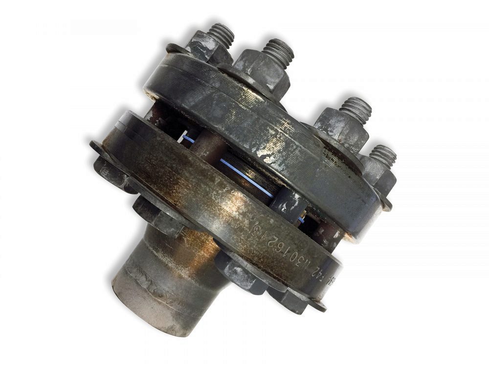
- 2. Understand how a gasket & flange work together as part of a BFJA
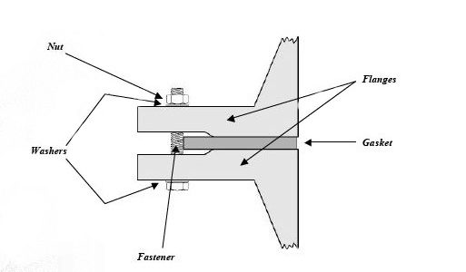
Figure 2: Bolted Joint Flange Assembly. Photo: Guidelines for Safe Seal Usage, Flanges and Gaskets. ESA/FSA Publication No. 009/98
The gasket is meant to create and maintain a static seal between two stationary, imperfect surfaces, containing a variety of liquids or gases under various service conditions. The surfaces or flanges must significantly compress the gasket to ensure a tight seal that has uniform pressure across it, despite any physical damage, like pits or dents. Mating flanges connected by a sealing device have serrations (roughness) on the faces that are meant to “bite” into the gasket material, effectively holding the gasket in place as it is compressed between the two flanges. As the compression happens, forces try to push the gasket material outwards. By holding the gasket in place, the installer is able to compress the seal and achieve desired tightness. The hole in the centre of the ring gasket will compress inwards slightly but remain open to allow media to pass through the pipe.
- 3. Take apart flange and assess for damage
When replacing gasket material in a BFJA or performing maintenance, pay attention to the flange face. Note any visual defects or damage – marks, scratches, dings or anything that changes the serrations on the flange face that can affect the flange’s ability to “bite” into gasket material. If so, reference PCC-1 for the maximum allowable defect depth and determine if the flange is suitable for service.
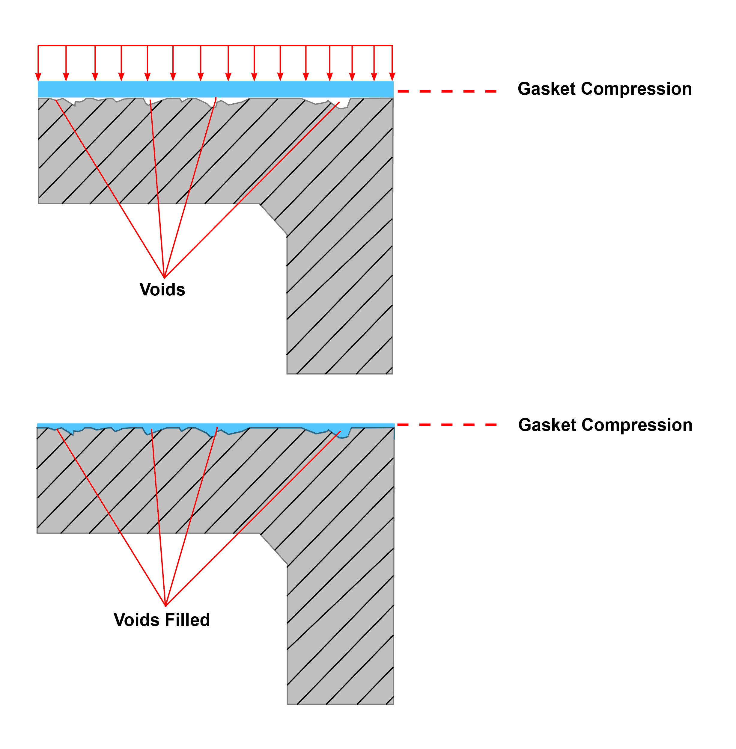
- 4. Identify a compressible gasket material that can fill imperfections
There is a high probability that damaged flanges could be a factor in BFJA failures. Warped and damaged flanges need to have imperfections filled by a compressible gasket material that can “bounce back” or recover with the flange and prevent leak paths from forming. Because this is widely known, installers believe installing a thicker gasket will solve the problem. However, what they do not take into account is that the thicker the gasket, the more creep will occur and paired with the inevitable decrease of force on the gasket, a gasket failure could result. The more that creep relaxation occurs, the higher the chance of a blowout.
When using smooth face finishes, such as those usually found in machinery or flanged joints other than pipe flanges, it is important to consider using a thinner gasket to lessen the effects of creep and cold flow. It should be noted, however, that both a thinner gasket and the smooth finish, in and of themselves, require a higher compressive force (i.e. bolt torque) to achieve the seal.
Durlon low emission gaskets for damaged flanges
Durlon PTFE –compressible gaskets with low creep properties suited to a wide range of service conditions and aggressive chemicals
Durlon ePTFE – highly compressible and versatile biaxially stretched PTFE product that conforms well in worn flanges and can handle a wide range of aggressive chemicals
Durlon ePTFE with metallic core – Durlon Durtec gaskets are virtually uncrushable under recommended loads and are an excellent low-emissions sealing gasket, paired with the conformability of ePTFE on both sides to suit imperfections on flange faces
Durlon SWGs (spiral wound gaskets) – winding density can be altered to allow conformability of SWGs
- 5. Determine correct thickness
A general rule of thumb for gasket thickness, is that if your flanges are in good condition and under 10” NPS the industry standard is to use 1/16” thickness. For flange sizes 10” NPS and larger the recommended thickness is 1/8”. If a previously installed PTFE gasket is removed and the serrations of the flange protrude through the material, this indicates that perhaps the gasket material being used is too thin and a thicker material should be used. In most industrial sealing applications, 1/32” is the minimum thickness that should be used, depending on the roughness or extent of damage on the flange face.
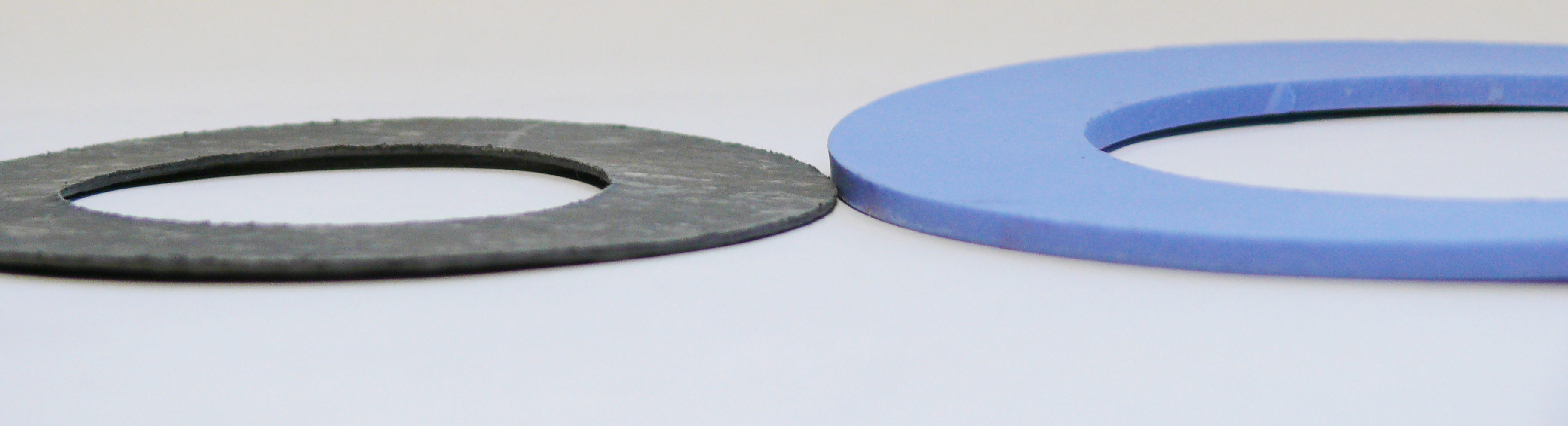
Figure 3: Gasket thicknesses; Left – 1/16″; Right – 1/8″
Note: Regardless of thickness, all of the other standard gasket qualifications must be met including bolt load, chemical resistance, working temperature/pressure ranges, material recovery, systematic thermal cycling, etc.
- 6. Take extra time installing & use proper torque values
It’s best to take a little extra time when installing a gasket between damaged flanges as improper installation causes approximately 85% of flange gasket failures and can greatly impact plant safety and piping structural integrity. If a single void is left unfilled, the gasket buckles or pinches, a leak path will be created. Be sure the reference the correct torque values by flange size and gasket style/class. Torque values are made readily available by the gasket manufacturer; Durlon torque values can be found on pages 49-53 of the Durlon Gasket Manual.
- 7. Add extra passes to bolting “star pattern” in assembly procedure
As an installer begins incremental tightening with the standard “star pattern” bolting assembly, additional passes will ensure the gasket is flat against the flange face. Concentration points forming over pits and marks will increase stress in those areas and possibly crush the gasket in certain places. Extra passes are especially important on worn flanges when serrations don’t “bite” into the gasket and hold it in place. For a printable Bolt Tightening Worksheet, click here.
- 8. Re-torque
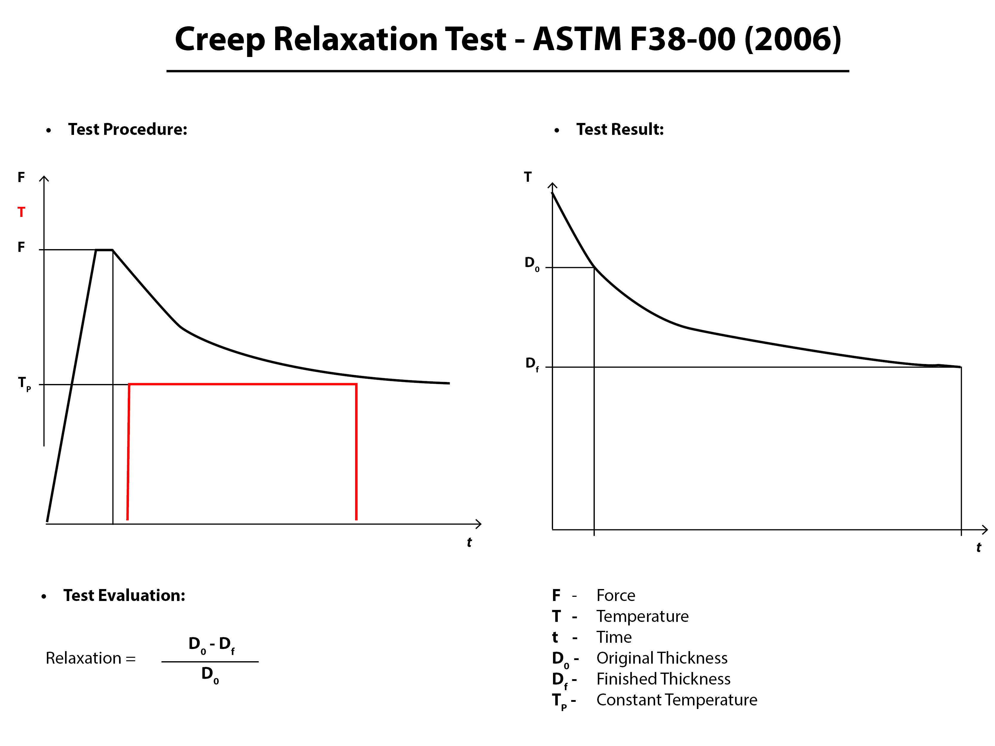
The gasket will inevitably relax, with the majority of creep-relaxation happening between 4-20 hours after the initial installation and must be re-torqued. This is a step that is frequently missed in many day-to-day gasket installations, in part because downtime is not an option for many. An even bigger issue, is when those installers fire up a system right away and re-tighten when the system is hot. This is known as hot-torquing and is not recommended. When a soft gasket material, such as compressed non-asbestos is hot-torqued, the material can crack as it becomes brittle when elastomer based material comes into contact with elevated temperatures.
- 9. Keep a record of damaged flanges and record leak rates
Keep a detailed record of which flanges in your systems are damaged, so that the same installation procedure can be used.
- 10. Replace gaskets or flanges when necessary
In many cases, an imperfect flange won’t be cut off and replaced, but when sealing with environmental compliance in mind, it is best to ensure that leaks are properly identified, recorded and dealt with. In some cases, this means replacing gaskets more frequently, especially if stress concentrators over dents/scratches are causing issues. It is best practice to not re-use gaskets unless direct application and user experience suggests it is safe to do so.
Main Takeaways
Slowing down and properly assembling a flange gasket connection can help companies meet environmental mandates by reducing emissions in BFJA’s. Be sure to properly assess physical flange damage on a flange surface and reference PCC-1. The imperfections seen may be well within the recommended guidelines for use by ASME. If you do have some damage to contend with, consider using a thicker, more compressible gasket material to fill imperfections, effectively preventing leak paths. Become familiar with proper bolt-up procedures and understand how much compression is needed if the switch is made to a thicker, softer material. Avoid firing up any systems immediately after installation and observe and record how the new BJFA performs compared to others.
For sealing solutions for damaged flange surfaces or detailed instructions on low emissions sealing, fill out this form.
You may also like…
Can Low Gasket Load Applications Meet Upcoming Fugitive Emissions Requirements?
What Does Gasket Installation Really Cost Your Plant?
How Long Will A Bolted Flange Gasket Last?
November 14, 2016
By: Bruce Ellis
It’s fall and for some, still warm – but it won’t be long until another heating season begins. Some facilities are already seeing the restart of boilers, and so, I’ve decided to address a cold weather issue that often arises with industrial steam and water boilers this time of year: they don’t start. Is there anything worse than a service call at 3 AM in January when the temperatures outside drop to -20°C? Once you have eliminated each component in your boiler as a possible culprit to boiler failure and it comes down to a check valve sticking open or closed in your system, it’s time for a replacement.
Each boiler is unique in the way it is designed and your choice in replacement will be somewhat dependent on the specifications your system requires. Whether you have a liquid, gas or steam boiler, this introduction to DFT Inc.’s three most common check valves for HVAC service is sure to get you warmed up to a replacement valve.
Note: DFT also manufactures check valves for use in large industrial boiler systems. A complete guide can be found here.
BASIC CHECK VALVE
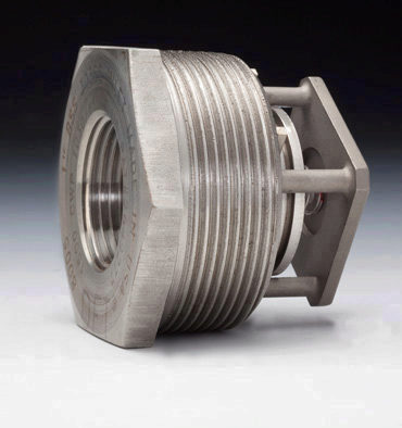
This proven check valve is suitable for a wide range of applications and is extremely versatile due to its ability to work at various pressures and temperatures. The Basic Check Valve can be made in different grades of stainless steel and is available from ¼” – 2 1/2” line sizes. The basic check can be used in installations requiring a CWP of 450-6,000 psi. DFT also manufactures the Basic Check with higher cracking pressures, from 2-40 psi. While the Basic Check is versatile, be sure to reference DFT Inc.’s full Catalogue for certain restrictions.
SCV CHECK VALVE
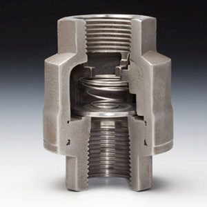
The most common check valve for use in steam applications, the SCV is also commonly used with liquid and gas. It uses the same trim as the Basic Check, in a durable body made of either 316 stainless steel, Alloy 20 or Hastelloy alloys with either FNPT or socket end welds. DFT SCV’s are available for ½”-3” pipe sizes and either 750 or 3,600 CWP. The SCV-R (Restrictor Check) is designed for higher cracking pressures than the standard SCV check valve. For a more simplified and flanged version of the SCV check valve, available in ASME Class 150 and 300, see DFT’s DLC check valve.
FBC CHECK VALVE
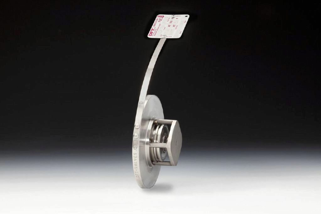
If you have an existing system with limited space – check this little space-saver out. The FBC “insert wafer” check valve is designed to be installed between two flanges and uses the same proven technology as the Basic Check valve. Though small, the FBC is made to last with stainless steel construction and a well-protected spring, not to mention the FBC can withstand temperatures up to 232°C (450°F). The FBC check valve works with schedule 40 pipe in the most common sizes 1”-4”, pressure class 150/300.
DFT Check Valves Used Extensively in HVAC
The simplicity and durability of DFT Valves has been proven since the original design dates back to the 1940’s and remains unchanged to this day. The non-slam, spring-assisted design prevents reverse flow and virtually eliminates water hammer in your system. All of DFT’s check valves are capable of water-tight shutoff, are easy to maintain, can be installed in any direction and are built to last. Our distributors and end-users tell us that “they last too long” and regularly comment on their unsurpassed design and efficiency. If you would like to learn more about DFT check valves for industrial steam, water or HVAC, let us know, we’re here to help.
Additional Resources
Design for Flexibility: Key Considerations to Make When Designing Fluid or Gas Flow Systems
DFT Check Valve Success Studies
Check Valve Application Data Sheet