July 19, 2016
Fugitive emissions are a red hot topic right now – and for good reason. With ever-increasing environmental awareness, leakage and how to prevent and reduce leaks should be on everyone’s mind. As a gasket manufacturer, it is Triangle Fluid Controls job to design, develop and educate end users on products that can help them meet upcoming low emission regulations.
Common class 150# flanges are well known as a stubborn culprit when trying to seal flanged connections – particularly 3” and 8” lines sizes. In the case of 150# flange design, an installer cannot apply enough load to the gasket due to either bolting, flange or material constraints. Another consideration is that with full face (FF) gaskets, you are trying to seal about 2-3 times the area of a ring gasket for raised-face (RF) flanges. You might ask,
“If I can’t apply more load to the gasket, how can I increase gasket load stress?”
Although it is case-by-case scenario, you have two options:
1) Reduce gasket sealing area
2) Use a controlled swell gasket material to intensify gasket stress after installation
Continue reading to determine the best option for your application.
Option 1: Reducing Gasket Area
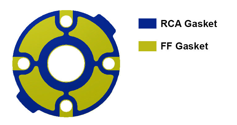
Reducing the gasket area is extremely effective and usually one of the easiest ways to increase gasket load, when not enough load can be applied to the gasket. Remember that Pressure= Force/Area, so if we can decrease the area, the pressure (in this case the seating stress) will increase. Specifically, the Durlon RCA (Reduced Contact Area) gaskets and Durlon PTFE Step Ring gaskets are designed based on this concept. Both types of gasket are fairly unique, even though they reduce gasket area so that the gasket stress is increased. Durlon RCA type gaskets are ideal for full face (FF) flanges and FRP piping that require a tight seal, however, they cannot handle high bolt loads generally required for fugitive emissions or critical sealing applications. The skeleton of the RCA gasket resembles that of a full face (FF) one, except a large portion of the non-critical gasket area is removed for optimal sealing performance.
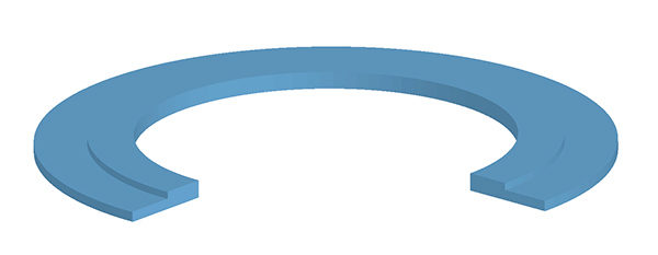
 Durlon 9000 Step Ring gaskets are like a ring gasket, except a portion of the sealing area is reduced by machining it on a CNC lathe from one piece of material. Traditionally, these type of gaskets are manufactured by laminating two gaskets of a thinner gauge and various size together with an adhesive. Aggressive chemicals, such as sulfuric acid, can quickly eat away at the adhesive after installation, which can lead to a premature leak path. PTFE Step gaskets are commonly found in sulfuric acid plants, and applications for PTFE Step Rings include 150# raised face (RF) (Floating) Lap Joint flanges, as well as MondiTM ductile iron sulfuric acid piping.
Option 2: Controlled Swell Gasket Material
In cases where the gasket area is already minimal and cannot be changed by design, or if reducing the gasket area simply isn’t enough, selecting a controlled swell material is a great option. These types of material really shine in low load applications that involve oil and water. Once the gasket is installed, the material swells when it makes contact with oils, fuel or water, which increases gasket thickness. As the material begins to “swell”, the gasket starts to expand, exerting force in both directions, against the flanges. Imagine a Belleville washer being compressed: by design, it applies force in the opposite direction, over the entire gasket-media contact zone and not just the fastener point-load zone. In theory, this is what a controlled swell material is doing. Durlon DuraSwellTM 7760 is a prime example of how choosing a high performance sealing material can negate less than ideal gasket sealing loads and still achieve a tight low to zero emissions seal.

Conclusion
So, can low stress sealing applications meet fugitive emissions requirements? My answer is absolutely. As always, I recommend contacting your gasket manufacturer and providing all of the necessary application details. This will allow a specialist to recommend the proper material and installation methods to ensure the best performing sealing device for your specific needs.
Until next time, stay safe out there, and keep the fluid between the pipes!
– TFC GasketGuru
Additional Resources
Durlon Duraswell 7760 Tech Sheet
TFC Ready to Help Canadian Energy Sector Reach New Emission Reduction Targets
What does gasket Installation Really Cost?
How long will a bolted flange connection last?
Gas problems? No need to raise a stink!
May 31, 2016
By: Bruce Ellis
If you work in natural gas processing and refrigeration, chances are you know the demands of storing and transporting gas. Compared to fluid sealing and discharge, the media flow isn’t steady, instead, gas “pulses” (through a pipeline) from a reciprocating compressor. This pulsating flow created by the compressor causes the discharge valves to chatter, and while the sound may not be high on your daily list of concerns, the resulting wear or damage to your check valve and downstream components can eventually lead to costly headaches. With the ever increasing global demand for natural gas, issues with check valves and piping systems after installation of a reciprocating compressor is something we see occurring more frequently.
The problem: an ineffective check valve for gas applications.
With natural gas production set to double by 2017 (U.S Energy Information Administration), producers must ensure that their systems are designed with quality parts. While sourcing quality equipment can be time consuming and result in large up-front costs, having the right parts installed in your system will ensure less time spent on maintenance, downtime, and fewer future costs. Ineffective discharge valves are more likely to create issues and suffer undue wear than using a check valve built with a damped design to control the valve’s moving parts. It’s not unheard of to learn of parts that have broken off of valves, damaging downstream components which may cause system failure.
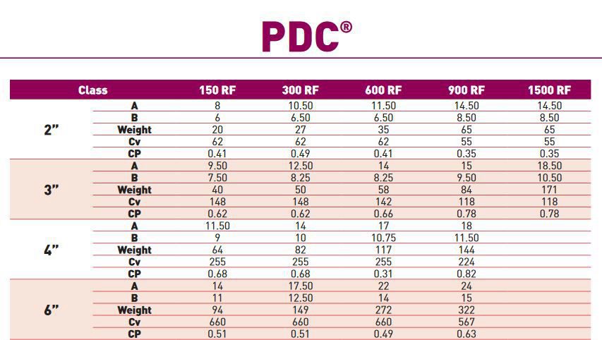
Built specifically for gas applications, DFT’s PDC check valve is a world-class solution found in oil refineries, gas pipelines, as well as storage and pump stations. Its pulse dampening chamber keeps the disc stable and in place (see below video). The PDC is also self-sizing, meaning it can handle different pressures and flow rates, without creating an issue or suffering undue wear. This flexibility extends the life of the valve. As an added benefit, the PDC can protect downstream equipment from damage that could be attributed to other types of valves if they fail.
The PDC check valve is manufactured to meet industry standards and can be built and tested to meet your company’s specifications. Available in various sizes and pressure classes, it can be manufactured using various metals, and is available with flanged, butt weld, or RTJ ends. If you would like to discuss your design needs, call us toll-free at 1-866-537-1133 or email bruce@trianglefluid.com.
Dimensions:
Additional Resources:
DFT Catalogue
Valve Data Sheet
Do you have an interesting idea for an industrial blog topic you would like to see covered? E-mail stephanie@trianglefluid.com.
March 22, 2016
When the conversation turns to gasket selection for high temperatures, things can get a little heated. The truth of the matter is that one person’s idea of a high temperature application is not the same as the next person’s.
Gasket temperature limits can be classified into (but are not limited to) the following temperature ranges:

Personally, I define high temperature applications as anything that exceeds the limitations of graphite alone. What I mean is that there are high temperature gasketing products such as the Durlon ETG (Extreme Temperature Gasket) series, that use a combination of super inhibited graphite with phyllosilicate materials to design a gasket that performs when exposed to heat and still has excellent sealability. Now don’t get me wrong, there are numerous critical applications that are below the 454°C/850°F threshold that still require high sealing performance at elevated temperatures. Using a gasket that has passed the API 607 Fire Test (with Exxon Modifications), should be taken into consideration when selecting a gasket for elevated temperatures and/or critical applications.
Moderate Temperature Gasketing
Compressed Fibre Gaskets (Max Temp: 400°C/750°F)
 Generally these gaskets are found in Class 150# and 300# applications. They perform quite well in low to moderate temperature applications, however, once introduced to elevated temperatures or steam they can become brittle due to their elastomer based binder. This can become problematic as when a gasket becomes brittle, it loses its ability to recover and if used in cyclic conditions, this can cause leaks. If a gasket is retightened after being introduced to temperature it can fracture causing a leak or gasket blowout. New advancements in filler material have allowed materials like Durlon 8900 to be developed that allow an increase in product temperature limitations, without the common brittleness found in other sheet materials. Durlon 8500 & Durlon 8900 have both passed the API 607 Fire Test.
Moderate – High Temperature Gasketing
Flexible Graphite (Max Temp: 450°C/850°F)
 Flexible graphite has been essential in industrial sealing applications and have been used in sheet gaskets and semi-metallic gaskets (Spiral Wound Gaskets, Kammprofiles and Corrugated Gaskets) for many years. In higher temperatures, graphite begins to oxidize which lessens the amount of material in the gasket (imagine looking at a piece of Swiss cheese). There are many factors that influence graphite oxidation such as graphite purity, density and surface area exposed to the oxidizing environment. Newer developments and additives such as oxidation inhibitors, slow down the rate of oxidation of graphite and can actually extend the temperature range of the material to 537°C/1,000°F. Such grades of graphite are classified as inhibited or super inhibited graphite (which is also known as Shell spec graphite). All Durlon semi-metallic gaskets have been manufactured using Shell Spec. graphite since late 2015.
High Temperature Gasketing
Phyllosilicate (Max Temp: 1,000°C/1,832°F)
When I think of high temperature applications, I think of gas turbines and burners, heat exchangers, exhaust manifolds and others commonly found in the refinery, power generation and chemical industries.
Phyllosilicate is a good choice when selecting a gasket for high temperature applications, for the following reasons:
- It’s flexible
- It’s elastic
- It has a high tensile strength
- It can withstand substantial mechanical pressure perpendicular to the lamellar plane
- It’s chemically resistant
- It’s fireproof
- It’s infusible
- It’s incombustible
- It’s non-flammable
- It’s a reliable alternative to asbestos
Durlon HT1000 consists of phlogopite mica “paper” impregnated with an inorganic binder at less than half the binder, amount found in vermiculite filled products. This lower binder content allows for superior weight retention, less than 4% weight loss at 800°C (1,472°F) and results in ultimate extreme temperature sealing performance up to 1,000°C (1,800°F).
So what does that mean?
In basic terms, it means that there will be more material present at higher temperatures, thus the leakage will be less than with other materials.
Final Thoughts
Hopefully this is a good jumping off point to aid in your search for high temperature gasket material. Just know, that this only begins to scratch the surface when trying to select a material for your critical application. As always, I would suggest contacting the gasket manufacturer to make sure you are using the best gasket material for your application. If you would like my help selecting a high temp gasket for your critical application, then complete and submit a Gasket Application Data Form. If you have any questions or comments, reach out to me as I am always up for discussing gaskets. You can find me on Twitter @TFGGasketguru or email me at tech@trianglefluid.com and bring the question heat!
Until next month, stay safe and keep the fluid between the pipes!
Additional Resources:
Gasket Material Selection Tool
Gasket Installation Video
Gasket Fundamentals
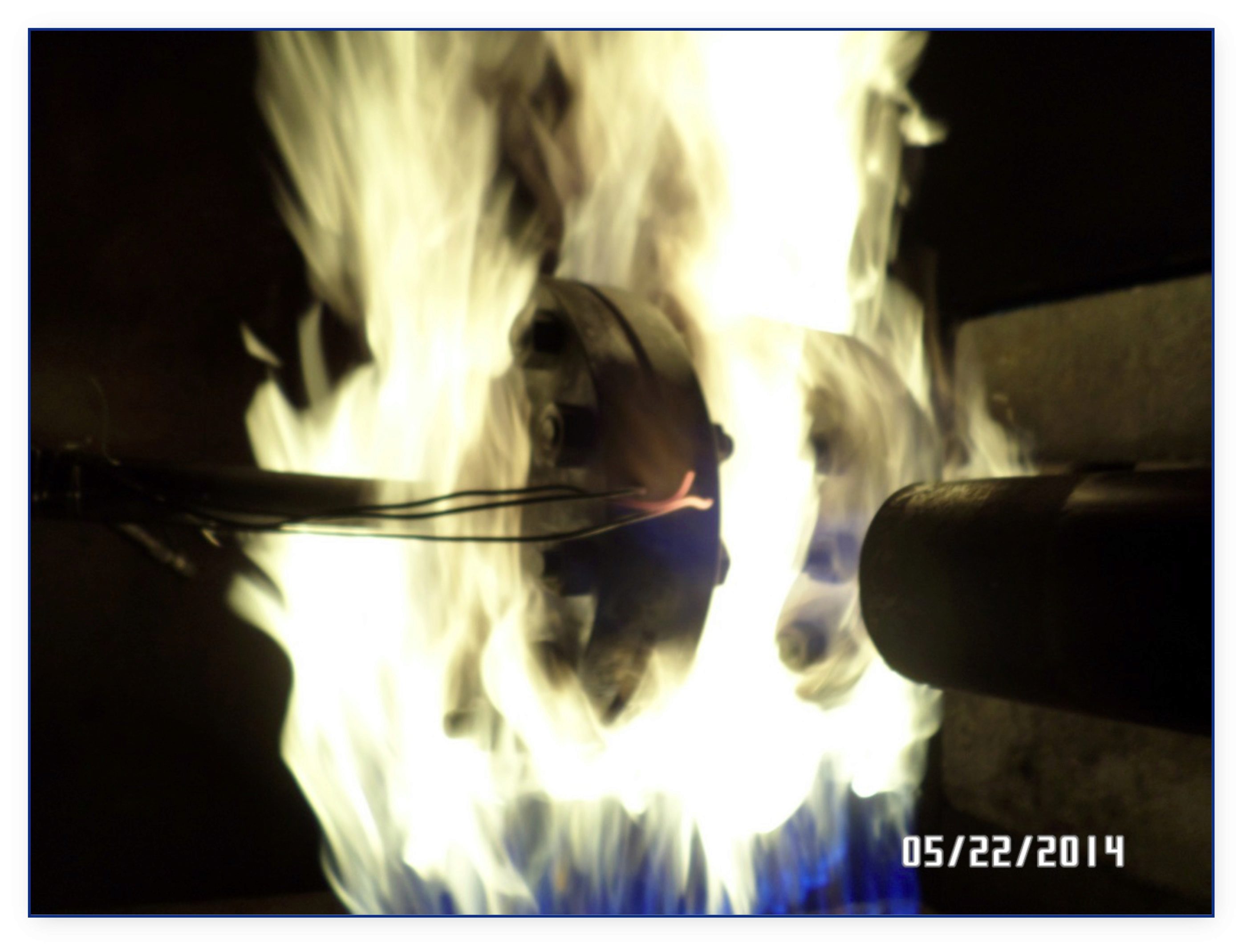
February 11, 2016
Contemplating what to write about this month, I was looking out the window of my office staring at the other plants in the business park with steam spewing from their towers and stacks. Like that, the topic came to me: this is the time of year that I like to refer to as “boiler season”. Many plants use steam for heating in addition to their standard processes, and with both fuel and water costs rising on an annual basis, just a small leak should not be taken lightly. In your hands-on role, have you ever truly thought about the actual cost of a correct gasket installation? To me (and not to complicate things) the short definition of a correct gasket installation is:
1. Choosing the correct gasket material for the application (refer to Gasket Material Selection Tool).
2. Obtaining the recommended torque values from the material manufacturer.
3. Using a properly accredited bolt tightening procedure (refer to ASME PCC-1).
4. Wear the proper PPE.
What Will a Steam Leak Cost?
To help paint a picture, I would like to use a familiar scenario. For this scenario, we have two pipe fitters: Bob and Joe. Both employees work at similar companies in town with the exact same amount of experience and training. Bob places a high degree of importance on the installation of gaskets in his plant, whereas Joe prides himself on how fast he can install the gasket and move on to the next task. Below is a side by side comparison of Bob and Joe’s installation of each gasket in the same application in a single bolted flange connection and the associated costs over a short, 12-day period.
The Cost of a Correct Gasket Installation
|
||
Day |
Bob | Joe |
1 |
Proper installation Time (25 min.) |
Improper installation Time (10 min.) |
2 |
No leak detected.
|
s A leak is visually detected within 12 hrs of installation (needs tightening). s |
10 |
No leak detected. | a
a a |
12 |
No leak detected. | s s Gasket has ruptured due to overtightening, steam is pouring out (replace gasket). s |
Analysiss
|
1 Gasket:$ 8.65 Labour: $12.50 Lost Steam:$ 0.00 Total Cost: $21.15 – Actual cost per day: $1.76 and declining with each day that passes. |
2 Gaskets: $17.30 Labour: $26.15 Lost Steam: $12.10 Total Cost: $55.55jkGJKGjkl k Actual cost per day: $4.63 and increasing with each day that passes if the installer continues to use the same gasket installation methods. a |
a
Based on this scenario, here are a few things to consider: Proper gasket installation is initially more time consuming but it improves your return on investment (ROI) – increasing operating profit by reducing overall downtime and gasket inventory requirements. This analysis is based on one 3” 150# bolted flange joint. Just think about how many bolted joints are in an average industrial facility, and just how many of these bolted joints leak on average.
Small Steam Leak = Big Cost
To help illustrate the costs associated with steam leaks, I have put together a bar graph using a steam loss calculator from American Plaint Maintenance, found at www.apmnortheast.com. The graph shows the average cost of a steam leak based on the diameter of the leak.
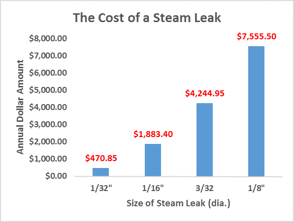
Now just imagine the above costs associated with 5, 10 or even 25 leaking bolted joint assemblies in your plant. Pretty scary thought, isn’t it?
Negative Impacts of Gasket Leaks
Finally, the most important part of installing a gasket correctly is the safety factor. I mean, what if the final failure occurred during the last retightening sequence? Joe could have been seriously burned which could have resulted in a loss time incident, heavy fines or even a lawsuit. Let’s not forget that there are also environmental considerations which failing to comply with could introduce hefty fines, negative media attention or even remediation. So regardless of how quickly you can get the gasket installed, for the small amount of time saved, is it truly worth the probable outcome of a gasket failure in the end?
Remember to check back in near future for upcoming discussions on gasket installation procedures. ‘Till then, remember to be smart, be like Bob, and keep the fluid between the pipes!
— TFC Gasket Guru
jkzlhklzjhvj;kz
Additional Resources:
Durlon Bolt Tightening Worksheet
Gasket Installation Video
Gasket Material Selection Tool
Triangle Fluid Controls Gasket Fundamentals
January 12, 2016
By: Bruce Ellis
We are going to discuss check valve flow orientation and position!
The issue can come from different requirements caused by pump design or space limitations. As we know, not all styles of check valves are suitable for different flow directions. It is important to consider this when designing a system so the correct check valve can be specified. This can increase the performance and life span of the components in your system. Given correct information, DFT axial flow centre guided check valves can be customized to most applications. If we know the media, its specific gravity and system design specifications, pressure, flow rate, temperature etc.; a valve can be customized to suit your application.
Horizontal Flow: This is the most common of the flow directions and all check valves will work in this situation. The question then becomes: “How do you chose one valve style over another?” It could be as simple as initial cost or lead time. This can be easily offset by the advantages centre guided valves have over swing check and dual door designs. The main benefit being the virtual elimination of water hammer, thus making the system more reliable and less troublesome. Maintenance and downtime are costly.
Vertical Flow (Up): This installation is common in mine de-watering and sump applications, or where space is at a premium. It is important to remember any foreign matter introduced into the system, such as sand, can settle on the closed valve causing it to not open or close properly. If we are aware of this, modifications can be made to help prevent the problem. Again, since spring assisted axial flow valves don’t require backflow to aid in closing, water hammer is not an issue and the system will work smoother.
Vertical Flow (Down): This is the most difficult flow direction for check valves to overcome. This orientation can be found in boiler supply lines and occasionally skid designs that are very space-limited. Some designs, such as swing checks, cannot be used in this situation, as they will open but not close. The spring assisted centre guided valves can be made to operate in this orientation. Given the static head pressure the valve is subject to, we can build the valve with a spring that allows for proper operation.
In closing, it is important to note that the greater the amount of information given, the easier it is to make an educated buying decision. DFT Check Valves come in different styles, wafer flanged and NPT, to satisfy most requirements. They are also available in exotic alloys and can be customized to suit most applications.
For more information please see the helpful resources below from www.dft-valves.com. We are here to help, so please contact us for any information you require.
Triangle Fluid Controls is the exclusive Canadian supplier of DFT Check Valves.
You May Also Be Interested In:
E-Book: Design for Flexibility: Key Considerations to Make When Designing Fluid or Gas Flow Systems
DFT Installation & Maintenance Manual
December 16, 2015

Have you ever received the dreaded 2 a.m. call from plant staff saying that things are at a standstill – production is down?
You arrive at the plant, walk through the parking lot, coffee in hand, and head to the locker room. When you come out on to the plant floor, there are several people staring at you with a look of panic on their faces as steam or process chemical sprays from a pipe flange.
Prognosis……gasket blowout.
You think to yourself “didn’t we just replace that gasket?”, or perhaps “we should have replaced it during the last shutdown but chose not to because of time constraints or cost cutting.”
If this scenario is new to you, you are lucky and you can go back to sleep… the 2 a.m. call was a wrong number. If it’s not new to you, this means you are most likely a Plant Supervisor, Maintenance Manager or Plant Personnel in some capacity.
Roll up your sleeves, grab your torque wrench and let’s get to work!
Gasket Lifespan
If I had a nickel for every time someone asked me, “How long will my gasket last?” I would be a rich man. As you can probably guess, “How long will my gasket last?” is a loaded question to which the practical, factual, and political answer is… an Application Engineer’s nightmare!
A gasket may last 5 years, or it could last 20 years. I cannot give you an exact date or lifespan of a gasket; however I can give you some insight into factors that will give your gasket the best chance at a long and prosperous life between the flanges.
3 Factors to Help Prevent Bolted Flange Gasket Blowout
1. Gasket Selection
Choosing the right gasket will save you a lot of grief. It’s important to speak with an Applications Engineer to help determine the proper gasket for your application. You can also use a free tool like iGasket to help determine a suitable gasket material. Factors such as chemical compatibility or elevated temperature can severely affect elastomer-based gaskets and cause them to become brittle. When gaskets become brittle they lose their ability to expand and contract with cyclic conditions. Sometimes they can start to leak slightly and the natural urge is to just “snug” or re-tighten the bolts with your wrench… DO NOT DO THIS.
Remember the gasket is brittle and now retightening this gasket may cause it to crack or break, leading to a blowout which can cause serious issues.
2. Gasket Quality
As a gasket manufacturer, I can tell you that cost matters. For instance a $2.00 compressed gasket may last 1 – 5 years, but a more expensive gasket such as a $25.00 Kammprofile gasket could last 20 years. You don’t necessarily need to buy the most expensive gasket on the market; however, saving 50¢ on a lower-priced gasket should not be high on your priority list forsaking reliability and safety. In the end, you get what you pay for (within reason).
3. Installation
Installation is the most important factor to gasket longevity. Failing to install a gasket correctly is starting off on the wrong foot and indeed setting yourself up for a premature failure. Consider the following before gasket installation:
Do you have an installation procedure?
Do you use a torque wrench?
Do you know what torque values must be used?
If you answered ‘No’ to any of the above questions, I highly suggest you reach out to your gasket manufacturer for recommended installation procedures, and appropriate torque values. Better yet – get your hands on a copy of ASME PCC-1 and read it if you’re serious about extending the life of your gaskets.
Spiral Wound Gaskets – The Durlon Difference!
By: Chett Norton, C.E.T
November 3, 2015
Spiral wounds gaskets ( SWGs) are a great multi-purpose gasket used in piping systems throughout the world. They are somewhat inexpensive, durable and in most cases readily available (pending metallurgical and filler requirements). The good thing about SWGs is that they can be used in all pressure classes, 150# up to and including 2500#. The design of spiral wound gaskets makes them blowout resistant and well accepted within the industry as a “Fire Safe” type of gasket.
Are all Spiral Wound Gaskets the Same?
The general assumption with spiral wound gaskets is that they are all the same. This is both true and false. Now I am going to play devil’s advocate on this. The reason I answered true is because all standard size spiral wound gaskets are typically manufactured to ASME B16.20, which is a dimensional manufacturing standard covering Metallic Gaskets for Pipe Flanges – Ring-Joint, Spiral Wound, and Jacketed (Gaskets). Also included in the publication of this standard are grooved metal gaskets with covering layers, otherwise known as Kammprofile gaskets. The most recent revision was published in 2012, hence, the current standard reference of ASME B16.20-2012. This standard covers gasket dimensional sizes in accordance to ASME B16.5 or B16.47 pipe flanges as well as the construction, metal joining, centering ring, inner ring, gasket compression and marking (general, pressure class and colour code) of the gaskets.
However, to answer the direct question, “Are all spiral wound gaskets the same?”, my answer would be no they are not. The reason for this is that things such as metal quality, filler quality (density, grade, thickness) and whether or not the gaskets were made on machines that control both pressure and tension on the gasket winding while being manufactured, ultimately control the final quality of the spiral wound gasket.
Spiral Wound Gasket Identification
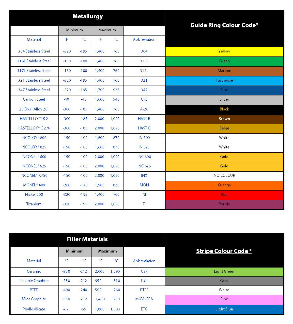
Spiral wound gaskets at times can seem to be very confusing with so many colours and stripes on them. However, it should be noted that using the ASME designation colour chart is pretty straight forward. The paint colour code system refers to the gaskets’ outer edge of the centering ring and the vertical stripes painted on the outer edge of the centering ring. The solid outer edge colour indicates the metal winding used and the vertical stripes indicate the filler used (see applicable charts below). Please note that the inner material should also match the winding material as noted in ASME B16.20-2012, unless specified by the user. For outer rings, the epoxy colour on the face of the rings is only brand specific, though some epoxies are more resistant to chemical attack and general atmospheric degradation. If the material of the centering ring is anything other than carbon steel, it will also be stamped on the ring.
Spiral Wound Gasket Constraints
The limiting factor in most cases for spiral wound gaskets is temperature. In general, it is the filler material that creates this limit.
Example:
For a 2” 300/400/600 spiral wound gasket construction of 304SS winding (760°C/1,400°F) and flexible graphite filler (510°C/950°F), the maximum temperature will be 510°C/950°F. This is governed by the flexible graphite filler even though the 304SS winding strip is rated to 760°C/1,400°C.
There are few exceptions to this rule and one of them is our Durlon® SWG DRI-ETG gasket. This gasket utilizes Durlon® HT1000® (Phlogopite Mica) material on both the ID and OD of the sealing element, while using super inhibited graphite in the middle of the sealing element for enhanced sealing capabilities. These layers of Durlon® HT1000® act as a heat shield or anti-oxidation layer and allow the gasket to seal up to 1,000°C/1832°F, where normal inhibited graphite is limited to approximately 565°C/1,050°F.
Benefits of Durlon® Spiral Wound Gaskets:
|
Spiral Wound Gasket Facts
- All gaskets should be supplied with an inner ring, unless the purchaser or end user specifies otherwise, as per ASME B16.20-2012 to help prevent inward buckling (see image).
- All PTFE filled SWGs shall have inner rings as per ASME B16.20-2012.
- For all other filler materials, inner rings shall be supplied in spiral wound gaskets in the below sizes/classes. (Higher bolt loads generated by the larger bolt diameter/quantity decrease the risk of inward buckling):NPS 24 and larger in Class 900
NPS 12 and larger in Class 1500
NPS 4 and larger in Class 2500 - Centering rings are not designed to be used as compression stops.
- Centering rings are carbon steel by default (epoxy coated or zinc electroplated to prevent corrosion), unless otherwise specified by the purchaser or end user. Carbon steel will not be stamped on the outer ring whereas materials such 304SS or 316SS will be.
Final Thoughts
In closing, spiral wound gaskets are still considered to be an existing technology or simple commodity. However, based on proper metallurgy selection and filler materials it can be a very innovative, engineered solution to today’s modern sealing challenges. So the next time you have to replace a gasket and you are unsure or have questions, ask yourself WWTGGD (What would the Gasket Guru Do?). You could also fill out the Gasket Application Data Form or call us (toll free) 866-537-1133.
By: Chett Norton, C.E.T & Alison Brent
Thursday, September 10, 2015
In the gasket industry there are a multitude of tests performed on materials that will supposedly help the end user make an educated decision on which material to use based on specific application criteria. However due to the lack of gasket property knowledge, what often ends up happening is that the end user becomes more confused, running the risk of choosing an incorrect material and causing untimely leaks or even unsafe gasket blowouts.
This article is intended to shed some light on four commonly misinterpreted and misunderstood gasket material tests: Flexibility (ASTM F147); Tensile Strength (ASTM D4745, ASTM F152); Sealability (ASTM F2378); and Maximum Pressure.
ASTM F147 – Standard Test Method for Flexibility of Non-Metallic Gasket Materials
This test method measures the gasket material’s Flexibility both transverse and longitudinal to the grain orientation. This test can also determine quality of the gasket material by determining the product’s Flexibility factor.
In this test, several “dog bone” shaped samples (based on the ASTM F147 standard) are cut in both transverse and longitudinal orientations. These samples are are placed in a conditioning oven at 100˚C (212˚F) for an hour then cooled to room temperature in a desiccator. The test material’s thickness is determined with a micrometer and recorded. The test material is firmly held at one point on a circular mandrel (ranging in diameter from 4.8mm to 101.6mm, starting with the largest diameter) and forced slowly to contact 180˚ of the full diameter. This procedure is repeated using decreasing mandrel diameters on a new sample until a failure occurs. A failure is considered to be any cracks, breaks, or surface separations at the end of the Flexibility test. When a failure occurs the mandrel diameter is recorded.
A Flexibility factor can be calculated by taking the Minimum Diameter divided by the Original Thickness. It is important to understand that when looking at the Flexibility factor the lowest possible value is considered a positive result. For example, Flexibility values are a lot like golf scores, meaning the lower the score, the better. Therefore, with Flexibility a value of 4 would be more flexible than a value of 10.
Tensile Strength (ASTM D4745 & ASTM F152)

At Triangle Fluid Controls we do 2 different types of Tensile testing using ASTM D4745 and F152 meaning we test both little “dog bones” and big “dog bones”. The test used is dependent on the type of material being tested, i.e. fiber, PTFE, and graphite. These “dog bones” are predetermined test specific shaped samples. Tensile testing is a quality control test by measuring the strength of the product, which in turn, determines the conformance of the manufacturing process. It should be noted that Tensile strength is not equivalent to the maximum pressure rating of the product, but more of a standard internal QA check.
ASTM D4745 – Standard Classification System and Basis for Specification for Filled PTFE Molding and Extrusion Materials
The ASTM D4745 Tensile test involves cutting material both transversely and longitudinally (conditioned based on sample type). These samples are then placed and clamped into our Tensile machine with an extensometer also attached to the sample. An extensometer is used to determine the strain measurement of the material under stress. The machine is then set up and parameters of the sample are imported. The machine is then started and runs until a failure occurs (any cracks, breaks, or surface separations at the end of the test). The results are recorded in psi and percent elongation.
ASTM F152 – Standard Test Methods for Tension Testing of Nonmetallic Gasket Materials
The ASTM F152 Tensile test is similar to the D4745 Tensile test except this test only involves samples to be cut transversely (conditioned based on sample type) and no extensometer is attached. These samples are then placed and clamped into the Tensile machine and the test is performed.
ASTM F2378 – Standard Test Method for Sealability of Sheet, Composite, and Solid Form-in-Place Gasket Materials
This test method is suitable for evaluating the leakage rate, sealing properties and characteristics of gasket materials under a load pressure at room temperature (21-30˚C/70-86˚F).
This testing process involves placing a cut sample (conditioned-based on sample type) using the ASTM F2378 specified die dimensions in between 2 flat steel platens. A seating load of 4,640 psi is applied and nitrogen is introduced into the center gasket cavity at a pressure of 580 psi. A timer is set for one hour, forty-five minutes. The evaluation stage occurs next as a manometer is connected to measure any leakage coming through or around the gasket. The leak rate is recorded at one minute, and again at fifteen minutes. The results are recoded and the average leak rate is calculated. The lower the average leak rate, the higher the gasket’s ability to seal. However there are many units used to measure Sealability (mL/min, cc/min or mL/hr) so you must make sure that you are comparing the correct test method and the reported units as well. Sealability is one of the most important characteristics in today’s sealing world, as even “small” leaks are frowned upon due to worker safety and environmental concerns.
Maximum Pressure
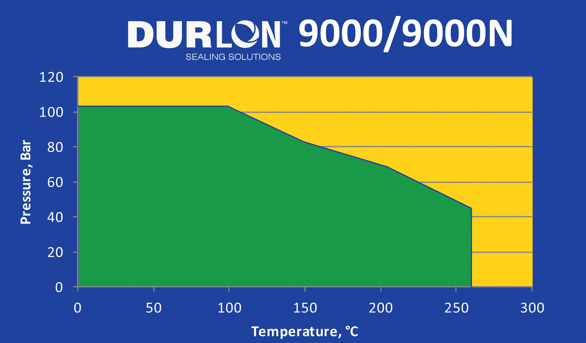
Maximum Pressure is used to determine a value where the material can be used safely (at room temperature). The material samples are pressurized until the gasket “blows” out and then using a FOS (Factor of Safety) a number can be determined, however it should be noted that in most cases, gasket materials are not used at room temperature. What we mean by this is that as gasket material is exposed to elevated temperatures the properties of the gasket change, so it is very important to check a PxT (Pressure x Temperature) chart for the material selected and your specific application (pressure, temperature, and media).
For instance, Durlon 9000 is rated for 1500psi, however as you can see in the below PxT chart at 400°F the maximum pressure would be 1000 psi. The Green area = safe to use; Yellow area = Do not use in these conditions or contact TFC applications engineering.
Final Thoughts
Hopefully this gives you a little more understanding and information on these four commonly misinterpreted and misunderstood gasket material tests, so that you can select a quality gasket material or at least be able to compare gasket materials on an “apples to apples” basis. If you are still unsure about gasket material selection, you can download our handy iGasket App, visit our website at www.trianglefluid.com or contact TFC application engineering (tech@trianglefluid.com). Chett Norton can also be reached via Twitter at @TFCgasketguru.