When it comes to finding the appropriate gasket material for your system, gasket selection can be one of two things: confusing or intimidating. Some are not sure where to begin, while others find the thought of dangerous leaks or costly shutdowns put them on edge. To help ease the selection process pain, we have developed a few simple tools that will help with gasket selection.
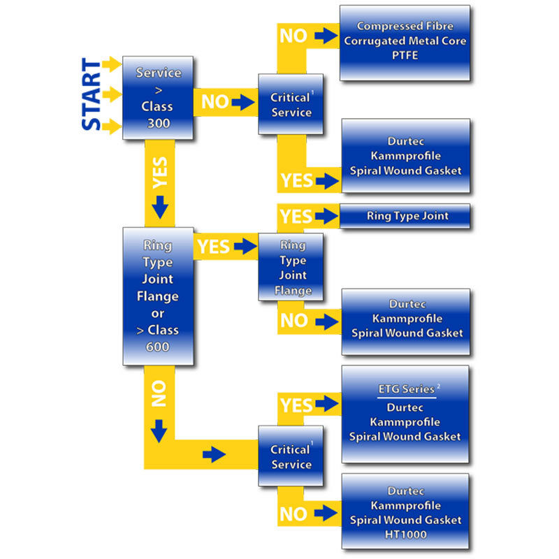
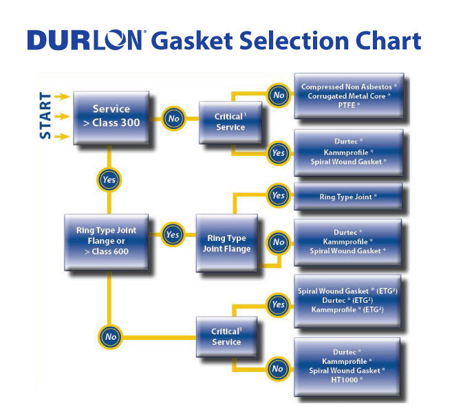
The first, a simple gasket flowchart, will help narrow down which Durlon sealing product is best based on a few simple operating condition guidelines.
-
- 1. Critical service can be any factor essential to plant operation or personnel/plant safety and can include environmental compliance. Failure or disruption of any critical service could result in serious impacts such as fines, time loss and/or injuries.
- 2. Durlon Extreme Temperature Gasket Series
*Note: This information is a general guide for the selection of a suitable gasket material. Triangle Fluid Controls does not accept responsibility for the misuse of this information.
How To Select
Gasket Material
No matter the gasket application there are always 3 things that need to be verified:
-
Pressure
-
Temperature
-
Media
Pressure x Temperature
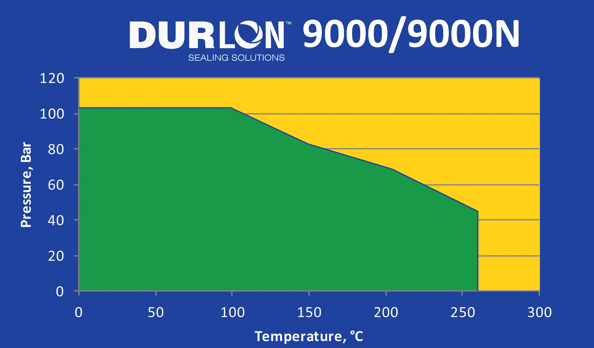
Gaskets are composed of and contain various binders, fillers, materials and metals. Each gasket type or material can have very specific pressure and temperature parameters that affect the performance of the gasket. For compressed non-asbestos and PTFE gasket materials, both temperature and pressure are critical and the result of not verifying these values could result in a leak or possibly a blowout. Generally, as the temperature increases, the material pressure rating decreases for that material. To help identify pressure and temperature limitations of a product, there are Pressure vs. Temperature charts (also known as P x T charts) that will essentially give you a “Yes” or “No” answer when selecting material. When the intersecting point of both the pressure and temperature of your application are inside the material boundary (green area below), it lets you know that material is safe to use for your application.

Media
Media can be verified by simply checking out a chemical resistance chart and verifying whether the material is chemically compatible. Unfortunately, most chemical compatibility charts are based on standard concentrations at room temperature, so you may find some ratings as ‘C’ for caution or ‘N/A’ for unknown. In these cases, contact TFC engineering for further information.
Here’s an easy tool we developed to help identify chemically compatibility (resistance). Click on the image to use the tool.

You should always feel confident that you are using the correct material for installation, but if you are still unsure, I highly recommend speaking with a trained applications engineer. Contact us to learn more about gasket selection from the fluid sealing experts at TFC.
Until next time, keep the fluid between the pipes!
May 4, 2017
Gasket installation seems like a simple concept:
You take a gasket, put it between two pipes, tighten the bolts and voilà…..it’s done.
Although this seems like a straightforward process, even to a seasoned veteran pipefitter, it can be tedious or downright scary if proper care is not taken during the installation process. To help with gasket installation, I have compiled a list of 6 of my favorite tools that will help even the most novice pipefitter install gaskets with ease. Before reading this list, you should already know how to install a gasket.
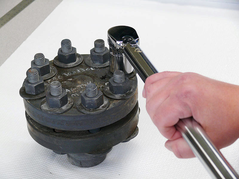
Torque Wrench
They can come in many shapes, sizes and styles ranging from the basic beam, clicker wrench or even electronic wrench. In 60% of gasket failures, the main cause of the failure is linked to under loaded gaskets. Applying the correct torque helps ensure that you are properly stretching the bolts, which in turn act like a spring pulling the flanges together, creating load on the gasket and achieving an effective seal. Torque wrenches can range in price and accuracy, however, despite the tool’s price tag, a torque wrench is only as good as it’s last calibration. So be sure to do this before putting it to use.
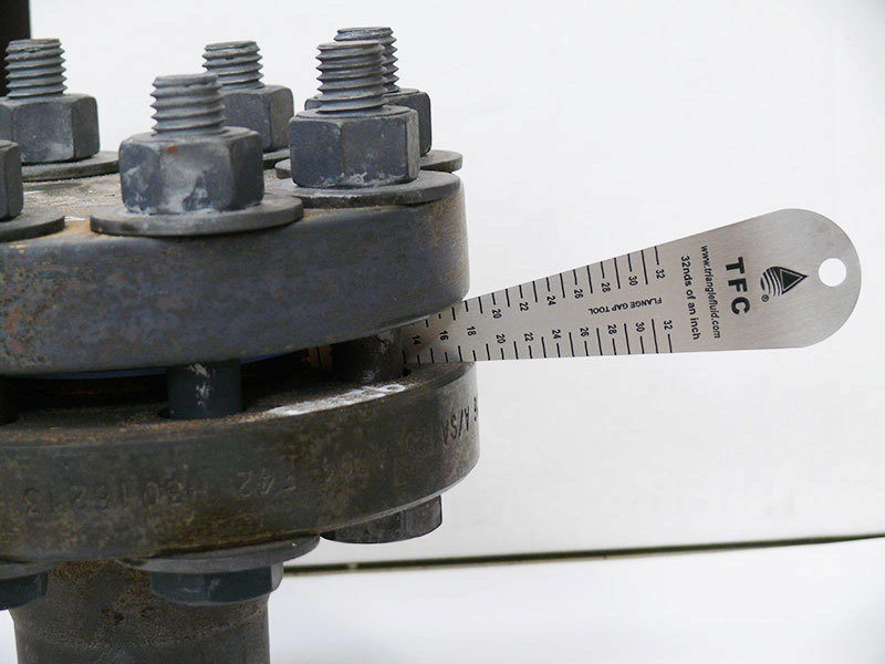
Gap Tools
These little dandies are very important in the gasket installation process. An important thing to remember is that bringing the flanges together in parallel ensures maximum contact between the flange and gasket. This transmits the most load that can be applied to the gasket, increasing the chance of success with your gasket installation. When you are tightening the bolts, it is important to measure the gap between the flanges, around the flange circumference in a minimum of 6 spots. If the gap is uneven, loosen or tighten the appropriate bolts until the gaps are within 1/32” (0.8mm). Once the flange gap spacing is evened out, you can continue with your cross star tightening pattern. The flange gap should be checked between every tightening round, paying special attention to first 2-3 passes.
Drift Pins
These hardened tapered steel pins aid in the alignment of flanges. Inserting a minimum of two drift pins into the flange bolt holes helps with two things: flange hole rotational alignment and centre line high/low alignment. After these pins have been inserted and the flanges are properly aligned, the bolts can be inserted with ease for future tightening.
Flange Spreader
Tight quarters or flanges that have very little spacing or clearance make it difficult to install a gasket and can increase installation time. Prying flanges apart with a bar or screwdriver is not a good idea, nor a safe one. Flange spreaders allow you to safely increase the gap between the flanges and give you enough room to remove the old gasket and insert a new one.
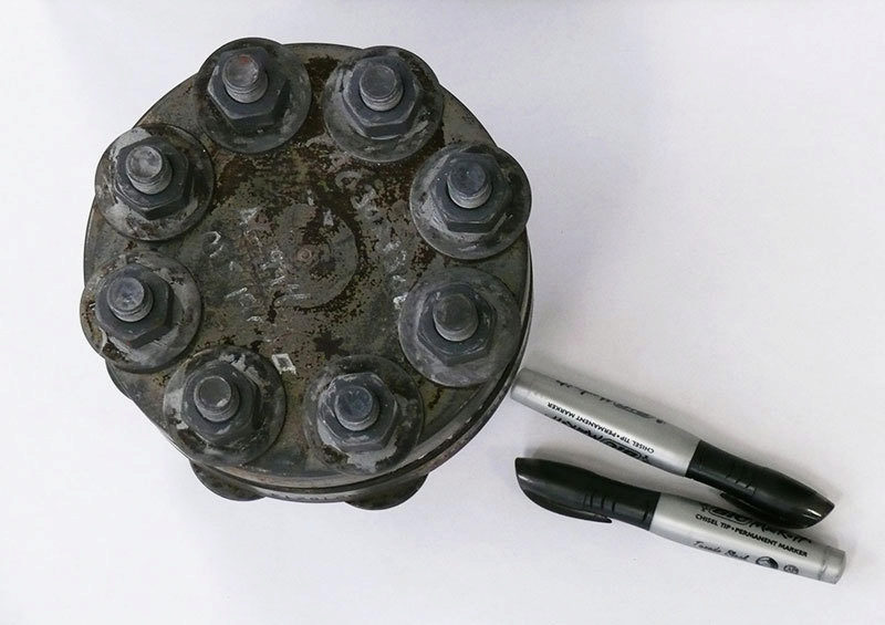
Sharpie
Perhaps one of the cheapest items on the list, but a useful one. A permanent marker such as a “Sharpie” allows you to number the bolts correctly so that you can follow a cross bolt tightening pattern during multiple rounds of tightening and not forget where you left off or which bolt is next.
This is not necessarily a physical tool, however, it can help a great deal with the installation procedure. These documents give the installer step-by-step instructions of the installation procedure in a check list format with the appropriate torque values for the installation. These sheets can also record the size, class, condition, bolting material, lubrication and installer. These installation details can be recalled at a later date and may help you will troubleshooting a problematic flange or a difficult sealing application based on previous installation history.
Hopefully you found my recommendations useful and have learned something new. If you haven’t tried any of the tools I mentioned, give them a try to compare things like ease of installation, tool usability, and installation time. Until next time, work safe, work smart and most importantly……keep the fluid between the pipes! If you would like more detailed information related to gasket installation, contact us.
1. Critical service can be any factor essential to plant operation or personnel/plant safety, and can include environmental compliance. Failure or disruption of any critical service could result in serious impacts such as fines, time loss and/or injuries.
2. Extreme Temperature Gasket Series
*See product descriptions for more information
NOTE: This selection chart is for general use only. For critical applications consult with Triangle Fluid Controls technical department. Triangle Fluid Controls does not accept responsibility for the misuse of this information.
January 26, 2017
By: Chett Norton, C.E.T and Stephanie Jouppien
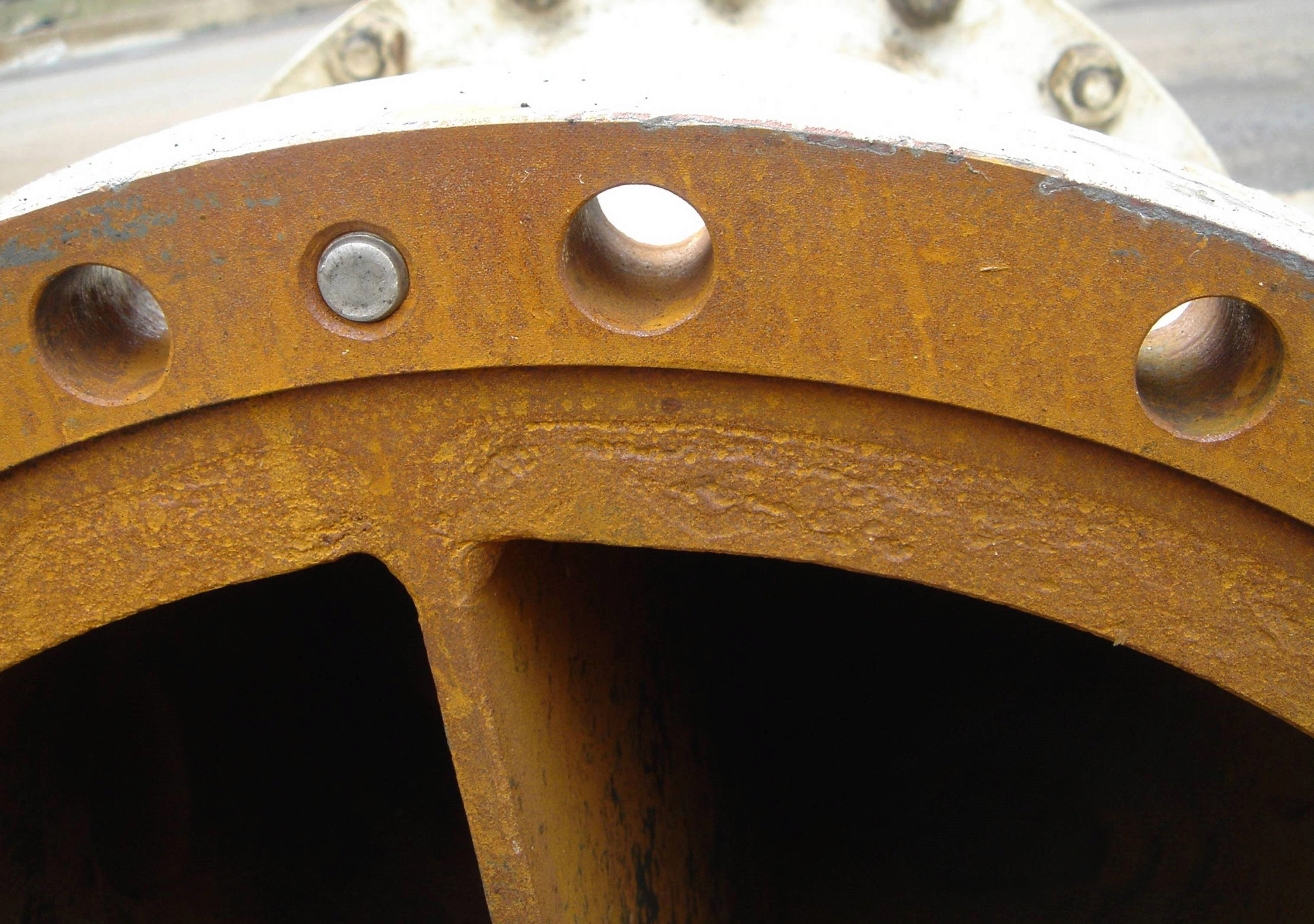
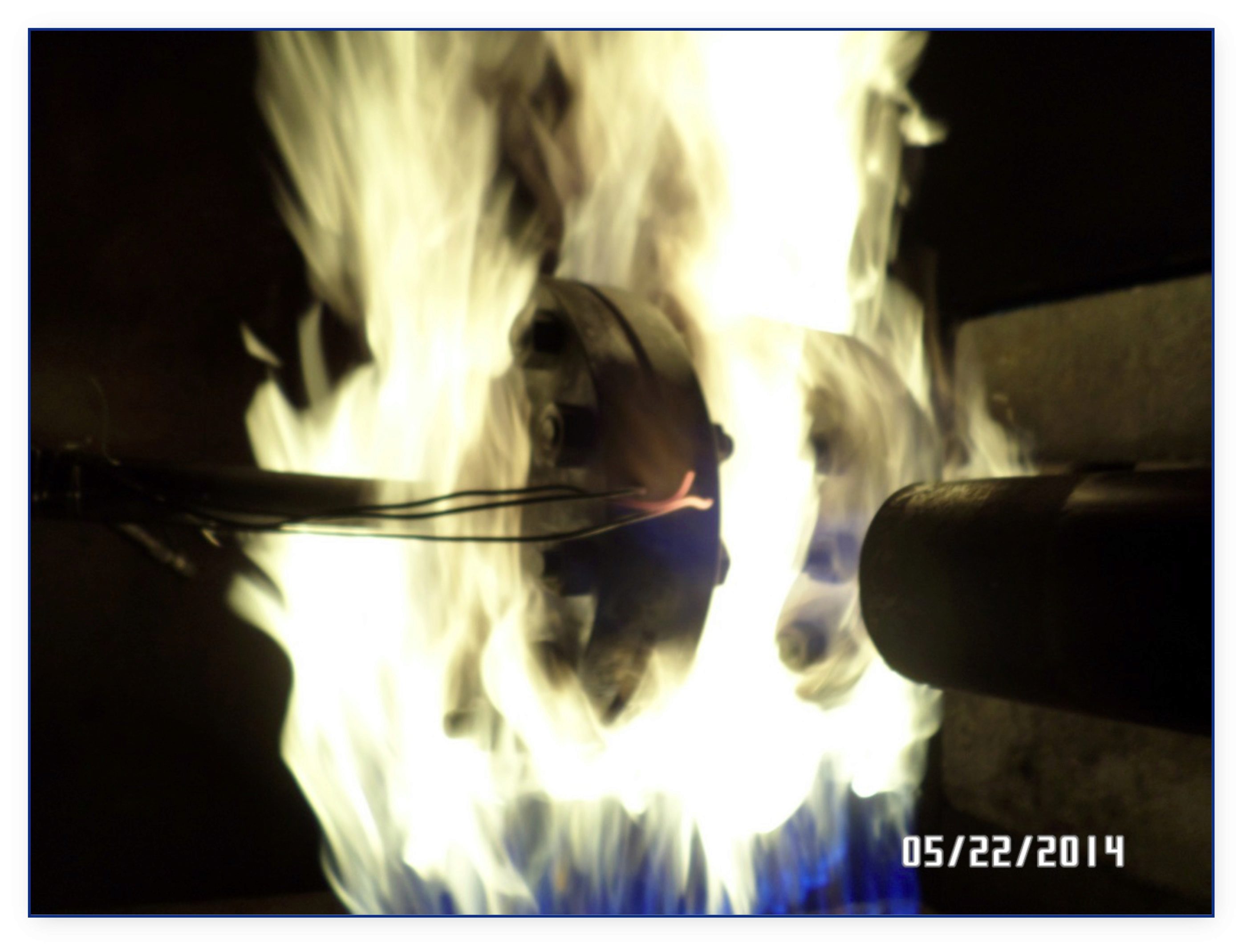
Figure 1: Pitted flange with steam cuts. Photo courtesy of Slade Inc.
Imperfections on flange faces happen. With regular maintenance and removing old, stuck-on gasket\debris, flanges with scratches, pits, dents and dings are a common site in many a plant. With more and more companies adopting low emissions business practices, can damaged flange surfaces seal to meet environmental compliance?
In the fluid sealing world, we know that flange surface is directly related to sealability and sealability is directly related to environmental compliance. As 85% of all known flange gasket failures are installation related, installers must take extra care when sealing damaged flange faces. Acknowledging the importance of proper gasket installation, we’ve compiled a list of 10 steps and considerations for diagnosing and overcoming flange damage.
10 Steps to Sealing Damaged Flange Surfaces
-
- 1. Get an updated copy of ASME PCC-1
ASME PCC-1 is unarguably the post-construction code bible of bolted flange joint assemblies (BFJA) in North America and following their published guidelines is best practice for bolting assembly procedures. A big benefit in using PCC-1 when sealing damaged flange faces is that it addresses the issue of working with imperfect flange faces and determines permissible amounts of damage that can still work as part of a BFJA and maintain an effective seal. Keep an eye out for updated versions of PCC-1 as fugitive emissions regulations become stricter.
- 1. Get an updated copy of ASME PCC-1
- 2. Understand how a gasket & flange work together as part of a BFJA
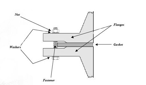
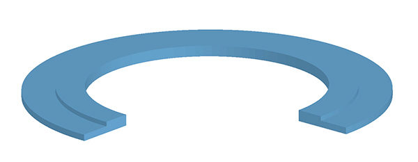
Figure 2: Bolted Joint Flange Assembly. Photo: Guidelines for Safe Seal Usage, Flanges and Gaskets. ESA/FSA Publication No. 009/98
The gasket is meant to create and maintain a static seal between two stationary, imperfect surfaces, containing a variety of liquids or gases under various service conditions. The surfaces or flanges must significantly compress the gasket to ensure a tight seal that has uniform pressure across it, despite any physical damage, like pits or dents. Mating flanges connected by a sealing device have serrations (roughness) on the faces that are meant to “bite” into the gasket material, effectively holding the gasket in place as it is compressed between the two flanges. As the compression happens, forces try to push the gasket material outwards. By holding the gasket in place, the installer is able to compress the seal and achieve desired tightness. The hole in the centre of the ring gasket will compress inwards slightly but remain open to allow media to pass through the pipe.
- 3. Take apart flange and assess for damage
When replacing gasket material in a BFJA or performing maintenance, pay attention to the flange face. Note any visual defects or damage – marks, scratches, dings or anything that changes the serrations on the flange face that can affect the flange’s ability to “bite” into gasket material. If so, reference PCC-1 for the maximum allowable defect depth and determine if the flange is suitable for service.
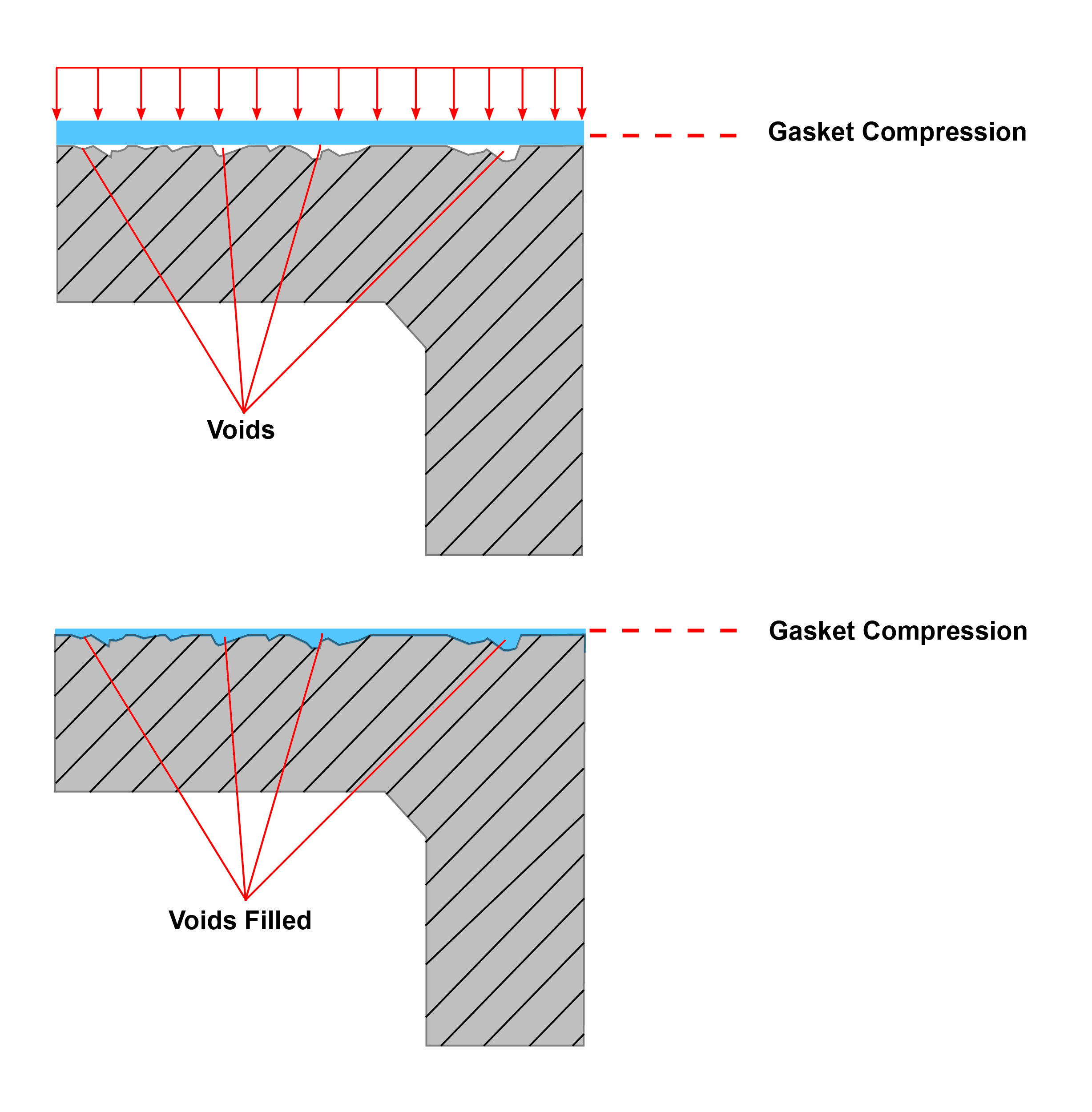
- 4. Identify a compressible gasket material that can fill imperfections
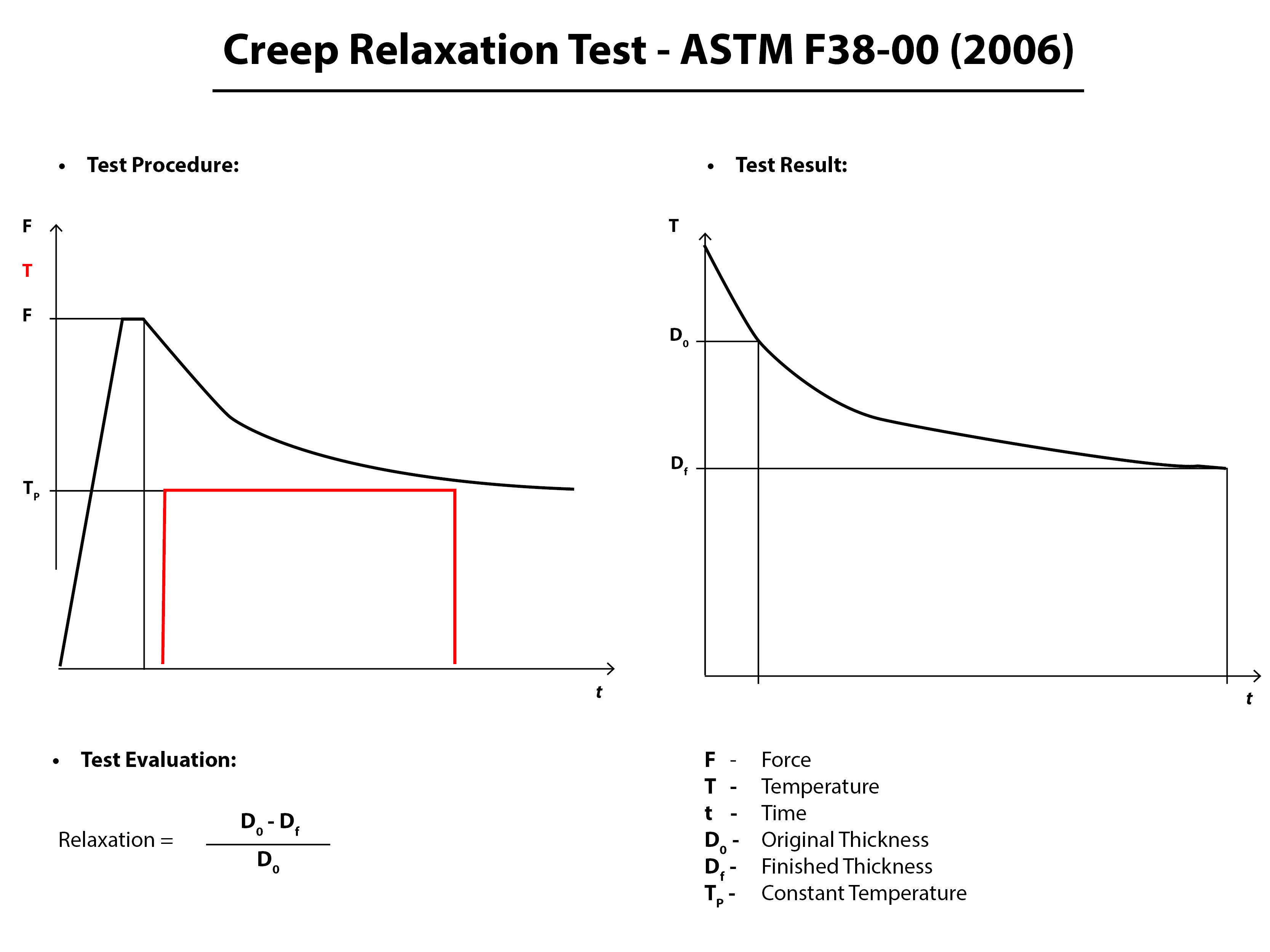
There is a high probability that damaged flanges could be a factor in BFJA failures. Warped and damaged flanges need to have imperfections filled by a compressible gasket material that can “bounce back” or recover with the flange and prevent leak paths from forming. Because this is widely known, installers believe installing a thicker gasket will solve the problem. However, what they do not take into account is that the thicker the gasket, the more creep will occur and paired with the inevitable decrease of force on the gasket, a gasket failure could result. The more that creep relaxation occurs, the higher the chance of a blowout.
When using smooth face finishes, such as those usually found in machinery or flanged joints other than pipe flanges, it is important to consider using a thinner gasket to lessen the effects of creep and cold flow. It should be noted, however, that both a thinner gasket and the smooth finish, in and of themselves, require a higher compressive force (i.e. bolt torque) to achieve the seal.
Durlon low emission gaskets for damaged flanges
Durlon PTFE –compressible gaskets with low creep properties suited to a wide range of service conditions and aggressive chemicals
Durlon ePTFE – highly compressible and versatile biaxially stretched PTFE product that conforms well in worn flanges and can handle a wide range of aggressive chemicals
Durlon ePTFE with metallic core – Durlon Durtec gaskets are virtually uncrushable under recommended loads and are an excellent low-emissions sealing gasket, paired with the conformability of ePTFE on both sides to suit imperfections on flange faces
Durlon SWGs (spiral wound gaskets) – winding density can be altered to allow conformability of SWGs
- 5. Determine correct thickness
A general rule of thumb for gasket thickness, is that if your flanges are in good condition and under 10” NPS the industry standard is to use 1/16” thickness. For flange sizes 10” NPS and larger the recommended thickness is 1/8”. If a previously installed PTFE gasket is removed and the serrations of the flange protrude through the material, this indicates that perhaps the gasket material being used is too thin and a thicker material should be used. In most industrial sealing applications, 1/32” is the minimum thickness that should be used, depending on the roughness or extent of damage on the flange face.
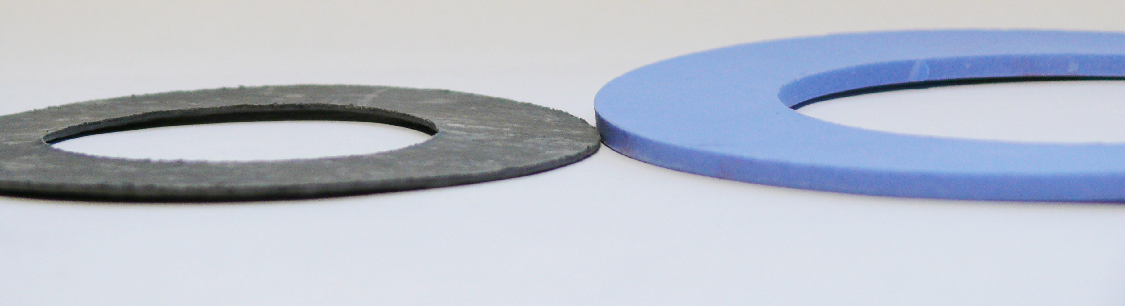
Figure 3: Gasket thicknesses; Left – 1/16″; Right – 1/8″
Note: Regardless of thickness, all of the other standard gasket qualifications must be met including bolt load, chemical resistance, working temperature/pressure ranges, material recovery, systematic thermal cycling, etc.
- 6. Take extra time installing & use proper torque values
It’s best to take a little extra time when installing a gasket between damaged flanges as improper installation causes approximately 85% of flange gasket failures and can greatly impact plant safety and piping structural integrity. If a single void is left unfilled, the gasket buckles or pinches, a leak path will be created. Be sure the reference the correct torque values by flange size and gasket style/class. Torque values are made readily available by the gasket manufacturer; Durlon torque values can be found on pages 49-53 of the Durlon Gasket Manual.
- 7. Add extra passes to bolting “star pattern” in assembly procedure
As an installer begins incremental tightening with the standard “star pattern” bolting assembly, additional passes will ensure the gasket is flat against the flange face. Concentration points forming over pits and marks will increase stress in those areas and possibly crush the gasket in certain places. Extra passes are especially important on worn flanges when serrations don’t “bite” into the gasket and hold it in place. For a printable Bolt Tightening Worksheet, click here.
- 8. Re-torque
The gasket will inevitably relax, with the majority of creep-relaxation happening between 4-20 hours after the initial installation and must be re-torqued. This is a step that is frequently missed in many day-to-day gasket installations, in part because downtime is not an option for many. An even bigger issue, is when those installers fire up a system right away and re-tighten when the system is hot. This is known as hot-torquing and is not recommended. When a soft gasket material, such as compressed non-asbestos is hot-torqued, the material can crack as it becomes brittle when elastomer based material comes into contact with elevated temperatures.
- 9. Keep a record of damaged flanges and record leak rates
Keep a detailed record of which flanges in your systems are damaged, so that the same installation procedure can be used.
- 10. Replace gaskets or flanges when necessary
In many cases, an imperfect flange won’t be cut off and replaced, but when sealing with environmental compliance in mind, it is best to ensure that leaks are properly identified, recorded and dealt with. In some cases, this means replacing gaskets more frequently, especially if stress concentrators over dents/scratches are causing issues. It is best practice to not re-use gaskets unless direct application and user experience suggests it is safe to do so.
Main Takeaways
Slowing down and properly assembling a flange gasket connection can help companies meet environmental mandates by reducing emissions in BFJA’s. Be sure to properly assess physical flange damage on a flange surface and reference PCC-1. The imperfections seen may be well within the recommended guidelines for use by ASME. If you do have some damage to contend with, consider using a thicker, more compressible gasket material to fill imperfections, effectively preventing leak paths. Become familiar with proper bolt-up procedures and understand how much compression is needed if the switch is made to a thicker, softer material. Avoid firing up any systems immediately after installation and observe and record how the new BJFA performs compared to others.
For sealing solutions for damaged flange surfaces or detailed instructions on low emissions sealing, fill out this form.
You may also like…
Can Low Gasket Load Applications Meet Upcoming Fugitive Emissions Requirements?
What Does Gasket Installation Really Cost Your Plant?
How Long Will A Bolted Flange Gasket Last?
July 19, 2016
Fugitive emissions are a red hot topic right now – and for good reason. With ever-increasing environmental awareness, leakage and how to prevent and reduce leaks should be on everyone’s mind. As a gasket manufacturer, it is Triangle Fluid Controls job to design, develop and educate end users on products that can help them meet upcoming low emission regulations.
Common class 150# flanges are well known as a stubborn culprit when trying to seal flanged connections – particularly 3” and 8” lines sizes. In the case of 150# flange design, an installer cannot apply enough load to the gasket due to either bolting, flange or material constraints. Another consideration is that with full face (FF) gaskets, you are trying to seal about 2-3 times the area of a ring gasket for raised-face (RF) flanges. You might ask,
“If I can’t apply more load to the gasket, how can I increase gasket load stress?”
Although it is case-by-case scenario, you have two options:
1) Reduce gasket sealing area
2) Use a controlled swell gasket material to intensify gasket stress after installation
Continue reading to determine the best option for your application.
Option 1: Reducing Gasket Area
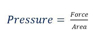
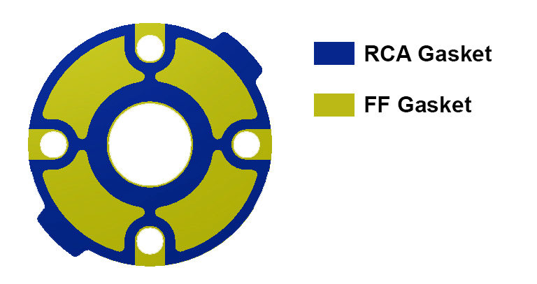
Reducing the gasket area is extremely effective and usually one of the easiest ways to increase gasket load, when not enough load can be applied to the gasket. Remember that Pressure= Force/Area, so if we can decrease the area, the pressure (in this case the seating stress) will increase. Specifically, the Durlon RCA (Reduced Contact Area) gaskets and Durlon PTFE Step Ring gaskets are designed based on this concept. Both types of gasket are fairly unique, even though they reduce gasket area so that the gasket stress is increased. Durlon RCA type gaskets are ideal for full face (FF) flanges and FRP piping that require a tight seal, however, they cannot handle high bolt loads generally required for fugitive emissions or critical sealing applications. The skeleton of the RCA gasket resembles that of a full face (FF) one, except a large portion of the non-critical gasket area is removed for optimal sealing performance.
 Durlon 9000 Step Ring gaskets are like a ring gasket, except a portion of the sealing area is reduced by machining it on a CNC lathe from one piece of material. Traditionally, these type of gaskets are manufactured by laminating two gaskets of a thinner gauge and various size together with an adhesive. Aggressive chemicals, such as sulfuric acid, can quickly eat away at the adhesive after installation, which can lead to a premature leak path. PTFE Step gaskets are commonly found in sulfuric acid plants, and applications for PTFE Step Rings include 150# raised face (RF) (Floating) Lap Joint flanges, as well as MondiTM ductile iron sulfuric acid piping.
Option 2: Controlled Swell Gasket Material
In cases where the gasket area is already minimal and cannot be changed by design, or if reducing the gasket area simply isn’t enough, selecting a controlled swell material is a great option. These types of material really shine in low load applications that involve oil and water. Once the gasket is installed, the material swells when it makes contact with oils, fuel or water, which increases gasket thickness. As the material begins to “swell”, the gasket starts to expand, exerting force in both directions, against the flanges. Imagine a Belleville washer being compressed: by design, it applies force in the opposite direction, over the entire gasket-media contact zone and not just the fastener point-load zone. In theory, this is what a controlled swell material is doing. Durlon DuraSwellTM 7760 is a prime example of how choosing a high performance sealing material can negate less than ideal gasket sealing loads and still achieve a tight low to zero emissions seal.

Conclusion
So, can low stress sealing applications meet fugitive emissions requirements? My answer is absolutely. As always, I recommend contacting your gasket manufacturer and providing all of the necessary application details. This will allow a specialist to recommend the proper material and installation methods to ensure the best performing sealing device for your specific needs.
Until next time, stay safe out there, and keep the fluid between the pipes!
– TFC GasketGuru
Additional Resources
Durlon Duraswell 7760 Tech Sheet
TFC Ready to Help Canadian Energy Sector Reach New Emission Reduction Targets
What does gasket Installation Really Cost?
How long will a bolted flange connection last?
March 22, 2016
When the conversation turns to gasket selection for high temperatures, things can get a little heated. The truth of the matter is that one person’s idea of a high temperature application is not the same as the next person’s.
Gasket temperature limits can be classified into (but are not limited to) the following temperature ranges:

Personally, I define high temperature applications as anything that exceeds the limitations of graphite alone. What I mean is that there are high temperature gasketing products such as the Durlon ETG (Extreme Temperature Gasket) series, that use a combination of super inhibited graphite with phyllosilicate materials to design a gasket that performs when exposed to heat and still has excellent sealability. Now don’t get me wrong, there are numerous critical applications that are below the 454°C/850°F threshold that still require high sealing performance at elevated temperatures. Using a gasket that has passed the API 607 Fire Test (with Exxon Modifications), should be taken into consideration when selecting a gasket for elevated temperatures and/or critical applications.
Moderate Temperature Gasketing
Compressed Fibre Gaskets (Max Temp: 400°C/750°F)
 Generally these gaskets are found in Class 150# and 300# applications. They perform quite well in low to moderate temperature applications, however, once introduced to elevated temperatures or steam they can become brittle due to their elastomer based binder. This can become problematic as when a gasket becomes brittle, it loses its ability to recover and if used in cyclic conditions, this can cause leaks. If a gasket is retightened after being introduced to temperature it can fracture causing a leak or gasket blowout. New advancements in filler material have allowed materials like Durlon 8900 to be developed that allow an increase in product temperature limitations, without the common brittleness found in other sheet materials. Durlon 8500 & Durlon 8900 have both passed the API 607 Fire Test.
Moderate – High Temperature Gasketing
Flexible Graphite (Max Temp: 450°C/850°F)
 Flexible graphite has been essential in industrial sealing applications and have been used in sheet gaskets and semi-metallic gaskets (Spiral Wound Gaskets, Kammprofiles and Corrugated Gaskets) for many years. In higher temperatures, graphite begins to oxidize which lessens the amount of material in the gasket (imagine looking at a piece of Swiss cheese). There are many factors that influence graphite oxidation such as graphite purity, density and surface area exposed to the oxidizing environment. Newer developments and additives such as oxidation inhibitors, slow down the rate of oxidation of graphite and can actually extend the temperature range of the material to 537°C/1,000°F. Such grades of graphite are classified as inhibited or super inhibited graphite (which is also known as Shell spec graphite). All Durlon semi-metallic gaskets have been manufactured using Shell Spec. graphite since late 2015.
High Temperature Gasketing
Phyllosilicate (Max Temp: 1,000°C/1,832°F)
When I think of high temperature applications, I think of gas turbines and burners, heat exchangers, exhaust manifolds and others commonly found in the refinery, power generation and chemical industries.
Phyllosilicate is a good choice when selecting a gasket for high temperature applications, for the following reasons:
- It’s flexible
- It’s elastic
- It has a high tensile strength
- It can withstand substantial mechanical pressure perpendicular to the lamellar plane
- It’s chemically resistant
- It’s fireproof
- It’s infusible
- It’s incombustible
- It’s non-flammable
- It’s a reliable alternative to asbestos
Durlon HT1000 consists of phlogopite mica “paper” impregnated with an inorganic binder at less than half the binder, amount found in vermiculite filled products. This lower binder content allows for superior weight retention, less than 4% weight loss at 800°C (1,472°F) and results in ultimate extreme temperature sealing performance up to 1,000°C (1,800°F).
So what does that mean?
In basic terms, it means that there will be more material present at higher temperatures, thus the leakage will be less than with other materials.
Final Thoughts
Hopefully this is a good jumping off point to aid in your search for high temperature gasket material. Just know, that this only begins to scratch the surface when trying to select a material for your critical application. As always, I would suggest contacting the gasket manufacturer to make sure you are using the best gasket material for your application. If you would like my help selecting a high temp gasket for your critical application, then complete and submit a Gasket Application Data Form. If you have any questions or comments, reach out to me as I am always up for discussing gaskets. You can find me on Twitter @TFGGasketguru or email me at tech@trianglefluid.com and bring the question heat!
Until next month, stay safe and keep the fluid between the pipes!
Additional Resources:
Gasket Material Selection Tool
Gasket Installation Video
Gasket Fundamentals
February 11, 2016
Contemplating what to write about this month, I was looking out the window of my office staring at the other plants in the business park with steam spewing from their towers and stacks. Like that, the topic came to me: this is the time of year that I like to refer to as “boiler season”. Many plants use steam for heating in addition to their standard processes, and with both fuel and water costs rising on an annual basis, just a small leak should not be taken lightly. In your hands-on role, have you ever truly thought about the actual cost of a correct gasket installation? To me (and not to complicate things) the short definition of a correct gasket installation is:
1. Choosing the correct gasket material for the application (refer to Gasket Material Selection Tool).
2. Obtaining the recommended torque values from the material manufacturer.
3. Using a properly accredited bolt tightening procedure (refer to ASME PCC-1).
4. Wear the proper PPE.
What Will a Steam Leak Cost?
To help paint a picture, I would like to use a familiar scenario. For this scenario, we have two pipe fitters: Bob and Joe. Both employees work at similar companies in town with the exact same amount of experience and training. Bob places a high degree of importance on the installation of gaskets in his plant, whereas Joe prides himself on how fast he can install the gasket and move on to the next task. Below is a side by side comparison of Bob and Joe’s installation of each gasket in the same application in a single bolted flange connection and the associated costs over a short, 12-day period.
The Cost of a Correct Gasket Installation
|
||
Day |
Bob | Joe |
1 |
Proper installation Time (25 min.) |
Improper installation Time (10 min.) |
2 |
No leak detected.
|
s A leak is visually detected within 12 hrs of installation (needs tightening). s |
10 |
No leak detected. | a
a a |
12 |
No leak detected. | s s Gasket has ruptured due to overtightening, steam is pouring out (replace gasket). s |
Analysiss
|
1 Gasket:$ 8.65 Labour: $12.50 Lost Steam:$ 0.00 Total Cost: $21.15 – Actual cost per day: $1.76 and declining with each day that passes. |
2 Gaskets: $17.30 Labour: $26.15 Lost Steam: $12.10 Total Cost: $55.55jkGJKGjkl k Actual cost per day: $4.63 and increasing with each day that passes if the installer continues to use the same gasket installation methods. a |
a
Based on this scenario, here are a few things to consider: Proper gasket installation is initially more time consuming but it improves your return on investment (ROI) – increasing operating profit by reducing overall downtime and gasket inventory requirements. This analysis is based on one 3” 150# bolted flange joint. Just think about how many bolted joints are in an average industrial facility, and just how many of these bolted joints leak on average.
Small Steam Leak = Big Cost
To help illustrate the costs associated with steam leaks, I have put together a bar graph using a steam loss calculator from American Plaint Maintenance, found at www.apmnortheast.com. The graph shows the average cost of a steam leak based on the diameter of the leak.
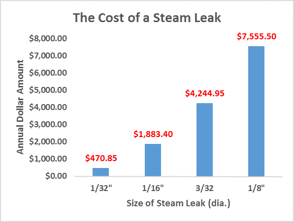
Now just imagine the above costs associated with 5, 10 or even 25 leaking bolted joint assemblies in your plant. Pretty scary thought, isn’t it?
Negative Impacts of Gasket Leaks
Finally, the most important part of installing a gasket correctly is the safety factor. I mean, what if the final failure occurred during the last retightening sequence? Joe could have been seriously burned which could have resulted in a loss time incident, heavy fines or even a lawsuit. Let’s not forget that there are also environmental considerations which failing to comply with could introduce hefty fines, negative media attention or even remediation. So regardless of how quickly you can get the gasket installed, for the small amount of time saved, is it truly worth the probable outcome of a gasket failure in the end?
Remember to check back in near future for upcoming discussions on gasket installation procedures. ‘Till then, remember to be smart, be like Bob, and keep the fluid between the pipes!
— TFC Gasket Guru
jkzlhklzjhvj;kz
Additional Resources:
Durlon Bolt Tightening Worksheet
Gasket Installation Video
Gasket Material Selection Tool
Triangle Fluid Controls Gasket Fundamentals
December 16, 2015

Have you ever received the dreaded 2 a.m. call from plant staff saying that things are at a standstill – production is down?
You arrive at the plant, walk through the parking lot, coffee in hand, and head to the locker room. When you come out on to the plant floor, there are several people staring at you with a look of panic on their faces as steam or process chemical sprays from a pipe flange.
Prognosis……gasket blowout.
You think to yourself “didn’t we just replace that gasket?”, or perhaps “we should have replaced it during the last shutdown but chose not to because of time constraints or cost cutting.”
If this scenario is new to you, you are lucky and you can go back to sleep… the 2 a.m. call was a wrong number. If it’s not new to you, this means you are most likely a Plant Supervisor, Maintenance Manager or Plant Personnel in some capacity.
Roll up your sleeves, grab your torque wrench and let’s get to work!
Gasket Lifespan
If I had a nickel for every time someone asked me, “How long will my gasket last?” I would be a rich man. As you can probably guess, “How long will my gasket last?” is a loaded question to which the practical, factual, and political answer is… an Application Engineer’s nightmare!
A gasket may last 5 years, or it could last 20 years. I cannot give you an exact date or lifespan of a gasket; however I can give you some insight into factors that will give your gasket the best chance at a long and prosperous life between the flanges.
3 Factors to Help Prevent Bolted Flange Gasket Blowout
1. Gasket Selection
Choosing the right gasket will save you a lot of grief. It’s important to speak with an Applications Engineer to help determine the proper gasket for your application. You can also use a free tool like iGasket to help determine a suitable gasket material. Factors such as chemical compatibility or elevated temperature can severely affect elastomer-based gaskets and cause them to become brittle. When gaskets become brittle they lose their ability to expand and contract with cyclic conditions. Sometimes they can start to leak slightly and the natural urge is to just “snug” or re-tighten the bolts with your wrench… DO NOT DO THIS.
Remember the gasket is brittle and now retightening this gasket may cause it to crack or break, leading to a blowout which can cause serious issues.
2. Gasket Quality
As a gasket manufacturer, I can tell you that cost matters. For instance a $2.00 compressed gasket may last 1 – 5 years, but a more expensive gasket such as a $25.00 Kammprofile gasket could last 20 years. You don’t necessarily need to buy the most expensive gasket on the market; however, saving 50¢ on a lower-priced gasket should not be high on your priority list forsaking reliability and safety. In the end, you get what you pay for (within reason).
3. Installation
Installation is the most important factor to gasket longevity. Failing to install a gasket correctly is starting off on the wrong foot and indeed setting yourself up for a premature failure. Consider the following before gasket installation:
Do you have an installation procedure?
Do you use a torque wrench?
Do you know what torque values must be used?
If you answered ‘No’ to any of the above questions, I highly suggest you reach out to your gasket manufacturer for recommended installation procedures, and appropriate torque values. Better yet – get your hands on a copy of ASME PCC-1 and read it if you’re serious about extending the life of your gaskets.
Spiral Wound Gaskets – The Durlon Difference!
By: Chett Norton, C.E.T
November 3, 2015
Spiral wounds gaskets ( SWGs) are a great multi-purpose gasket used in piping systems throughout the world. They are somewhat inexpensive, durable and in most cases readily available (pending metallurgical and filler requirements). The good thing about SWGs is that they can be used in all pressure classes, 150# up to and including 2500#. The design of spiral wound gaskets makes them blowout resistant and well accepted within the industry as a “Fire Safe” type of gasket.
Are all Spiral Wound Gaskets the Same?
The general assumption with spiral wound gaskets is that they are all the same. This is both true and false. Now I am going to play devil’s advocate on this. The reason I answered true is because all standard size spiral wound gaskets are typically manufactured to ASME B16.20, which is a dimensional manufacturing standard covering Metallic Gaskets for Pipe Flanges – Ring-Joint, Spiral Wound, and Jacketed (Gaskets). Also included in the publication of this standard are grooved metal gaskets with covering layers, otherwise known as Kammprofile gaskets. The most recent revision was published in 2012, hence, the current standard reference of ASME B16.20-2012. This standard covers gasket dimensional sizes in accordance to ASME B16.5 or B16.47 pipe flanges as well as the construction, metal joining, centering ring, inner ring, gasket compression and marking (general, pressure class and colour code) of the gaskets.
However, to answer the direct question, “Are all spiral wound gaskets the same?”, my answer would be no they are not. The reason for this is that things such as metal quality, filler quality (density, grade, thickness) and whether or not the gaskets were made on machines that control both pressure and tension on the gasket winding while being manufactured, ultimately control the final quality of the spiral wound gasket.
Spiral Wound Gasket Identification

Spiral wound gaskets at times can seem to be very confusing with so many colours and stripes on them. However, it should be noted that using the ASME designation colour chart is pretty straight forward. The paint colour code system refers to the gaskets’ outer edge of the centering ring and the vertical stripes painted on the outer edge of the centering ring. The solid outer edge colour indicates the metal winding used and the vertical stripes indicate the filler used (see applicable charts below). Please note that the inner material should also match the winding material as noted in ASME B16.20-2012, unless specified by the user. For outer rings, the epoxy colour on the face of the rings is only brand specific, though some epoxies are more resistant to chemical attack and general atmospheric degradation. If the material of the centering ring is anything other than carbon steel, it will also be stamped on the ring.
Spiral Wound Gasket Constraints
The limiting factor in most cases for spiral wound gaskets is temperature. In general, it is the filler material that creates this limit.
Example:
For a 2” 300/400/600 spiral wound gasket construction of 304SS winding (760°C/1,400°F) and flexible graphite filler (510°C/950°F), the maximum temperature will be 510°C/950°F. This is governed by the flexible graphite filler even though the 304SS winding strip is rated to 760°C/1,400°C.
There are few exceptions to this rule and one of them is our Durlon® SWG DRI-ETG gasket. This gasket utilizes Durlon® HT1000® (Phlogopite Mica) material on both the ID and OD of the sealing element, while using super inhibited graphite in the middle of the sealing element for enhanced sealing capabilities. These layers of Durlon® HT1000® act as a heat shield or anti-oxidation layer and allow the gasket to seal up to 1,000°C/1832°F, where normal inhibited graphite is limited to approximately 565°C/1,050°F.
Benefits of Durlon® Spiral Wound Gaskets:
|
Spiral Wound Gasket Facts
- All gaskets should be supplied with an inner ring, unless the purchaser or end user specifies otherwise, as per ASME B16.20-2012 to help prevent inward buckling (see image).
- All PTFE filled SWGs shall have inner rings as per ASME B16.20-2012.
- For all other filler materials, inner rings shall be supplied in spiral wound gaskets in the below sizes/classes. (Higher bolt loads generated by the larger bolt diameter/quantity decrease the risk of inward buckling):NPS 24 and larger in Class 900
NPS 12 and larger in Class 1500
NPS 4 and larger in Class 2500 - Centering rings are not designed to be used as compression stops.
- Centering rings are carbon steel by default (epoxy coated or zinc electroplated to prevent corrosion), unless otherwise specified by the purchaser or end user. Carbon steel will not be stamped on the outer ring whereas materials such 304SS or 316SS will be.
Final Thoughts
In closing, spiral wound gaskets are still considered to be an existing technology or simple commodity. However, based on proper metallurgy selection and filler materials it can be a very innovative, engineered solution to today’s modern sealing challenges. So the next time you have to replace a gasket and you are unsure or have questions, ask yourself WWTGGD (What would the Gasket Guru Do?). You could also fill out the Gasket Application Data Form or call us (toll free) 866-537-1133.
By: Chett Norton, C.E.T & Alison Brent
Thursday, September 10, 2015
In the gasket industry there are a multitude of tests performed on materials that will supposedly help the end user make an educated decision on which material to use based on specific application criteria. However due to the lack of gasket property knowledge, what often ends up happening is that the end user becomes more confused, running the risk of choosing an incorrect material and causing untimely leaks or even unsafe gasket blowouts.
This article is intended to shed some light on four commonly misinterpreted and misunderstood gasket material tests: Flexibility (ASTM F147); Tensile Strength (ASTM D4745, ASTM F152); Sealability (ASTM F2378); and Maximum Pressure.
ASTM F147 – Standard Test Method for Flexibility of Non-Metallic Gasket Materials
This test method measures the gasket material’s Flexibility both transverse and longitudinal to the grain orientation. This test can also determine quality of the gasket material by determining the product’s Flexibility factor.
In this test, several “dog bone” shaped samples (based on the ASTM F147 standard) are cut in both transverse and longitudinal orientations. These samples are are placed in a conditioning oven at 100˚C (212˚F) for an hour then cooled to room temperature in a desiccator. The test material’s thickness is determined with a micrometer and recorded. The test material is firmly held at one point on a circular mandrel (ranging in diameter from 4.8mm to 101.6mm, starting with the largest diameter) and forced slowly to contact 180˚ of the full diameter. This procedure is repeated using decreasing mandrel diameters on a new sample until a failure occurs. A failure is considered to be any cracks, breaks, or surface separations at the end of the Flexibility test. When a failure occurs the mandrel diameter is recorded.
A Flexibility factor can be calculated by taking the Minimum Diameter divided by the Original Thickness. It is important to understand that when looking at the Flexibility factor the lowest possible value is considered a positive result. For example, Flexibility values are a lot like golf scores, meaning the lower the score, the better. Therefore, with Flexibility a value of 4 would be more flexible than a value of 10.
Tensile Strength (ASTM D4745 & ASTM F152)

At Triangle Fluid Controls we do 2 different types of Tensile testing using ASTM D4745 and F152 meaning we test both little “dog bones” and big “dog bones”. The test used is dependent on the type of material being tested, i.e. fiber, PTFE, and graphite. These “dog bones” are predetermined test specific shaped samples. Tensile testing is a quality control test by measuring the strength of the product, which in turn, determines the conformance of the manufacturing process. It should be noted that Tensile strength is not equivalent to the maximum pressure rating of the product, but more of a standard internal QA check.
ASTM D4745 – Standard Classification System and Basis for Specification for Filled PTFE Molding and Extrusion Materials
The ASTM D4745 Tensile test involves cutting material both transversely and longitudinally (conditioned based on sample type). These samples are then placed and clamped into our Tensile machine with an extensometer also attached to the sample. An extensometer is used to determine the strain measurement of the material under stress. The machine is then set up and parameters of the sample are imported. The machine is then started and runs until a failure occurs (any cracks, breaks, or surface separations at the end of the test). The results are recorded in psi and percent elongation.
ASTM F152 – Standard Test Methods for Tension Testing of Nonmetallic Gasket Materials
The ASTM F152 Tensile test is similar to the D4745 Tensile test except this test only involves samples to be cut transversely (conditioned based on sample type) and no extensometer is attached. These samples are then placed and clamped into the Tensile machine and the test is performed.
ASTM F2378 – Standard Test Method for Sealability of Sheet, Composite, and Solid Form-in-Place Gasket Materials
This test method is suitable for evaluating the leakage rate, sealing properties and characteristics of gasket materials under a load pressure at room temperature (21-30˚C/70-86˚F).
This testing process involves placing a cut sample (conditioned-based on sample type) using the ASTM F2378 specified die dimensions in between 2 flat steel platens. A seating load of 4,640 psi is applied and nitrogen is introduced into the center gasket cavity at a pressure of 580 psi. A timer is set for one hour, forty-five minutes. The evaluation stage occurs next as a manometer is connected to measure any leakage coming through or around the gasket. The leak rate is recorded at one minute, and again at fifteen minutes. The results are recoded and the average leak rate is calculated. The lower the average leak rate, the higher the gasket’s ability to seal. However there are many units used to measure Sealability (mL/min, cc/min or mL/hr) so you must make sure that you are comparing the correct test method and the reported units as well. Sealability is one of the most important characteristics in today’s sealing world, as even “small” leaks are frowned upon due to worker safety and environmental concerns.
Maximum Pressure
Maximum Pressure is used to determine a value where the material can be used safely (at room temperature). The material samples are pressurized until the gasket “blows” out and then using a FOS (Factor of Safety) a number can be determined, however it should be noted that in most cases, gasket materials are not used at room temperature. What we mean by this is that as gasket material is exposed to elevated temperatures the properties of the gasket change, so it is very important to check a PxT (Pressure x Temperature) chart for the material selected and your specific application (pressure, temperature, and media).
For instance, Durlon 9000 is rated for 1500psi, however as you can see in the below PxT chart at 400°F the maximum pressure would be 1000 psi. The Green area = safe to use; Yellow area = Do not use in these conditions or contact TFC applications engineering.
Final Thoughts
Hopefully this gives you a little more understanding and information on these four commonly misinterpreted and misunderstood gasket material tests, so that you can select a quality gasket material or at least be able to compare gasket materials on an “apples to apples” basis. If you are still unsure about gasket material selection, you can download our handy iGasket App, visit our website at www.trianglefluid.com or contact TFC application engineering (tech@trianglefluid.com). Chett Norton can also be reached via Twitter at @TFCgasketguru.