2016 Randy McKay Award of Merit goes to…..

Triangle Fluid Controls (TFC) is pleased to award the 2016 Randy McKay Sales Award of Merit to Yves Pariseau, in recognition for his outstanding sales performance with TFC. The award is given to TFC’s Regional Sales Manager (RSM) whose territory had the largest year-over-year sales increase from 2015 – 2016 and was presented August 24, 2017 at TFC’s headquarters in Belleville, Ontario. “We are extremely pleased to award Yves Pariseau with the Randy McKay Award of Merit,” said TFC’s General Manager, Mike Boyd. “Yves has been a valuable member of the TFC Sales team since 2006. During his tenure, Yves has done a great job developing his territory in Eastern Canada and we are excited at the prospect of future revenue growth in this region of Canada.”

The award, created in memory of the late Randy McKay, TFC’s Central Canada RSM, was created by TFC President Mike Shorts, as a means of paying homage to the former TFC employee. “Randy did a lot for TFC, was a stand-up individual, and somebody that I personally, learned a lot about sales from. After Randy’s passing in 2015, I knew I wanted to create an award in his memory.”

The award includes two pieces: an engraved glass plaque and hand-blown glass sculpture made in a similar shape, style, and colouring to TFC’s company logo. The glass plaque will hang in TFC’s lobby with each year’s winner added to it. The making of the pieces, commissioned by a local glass blower in Wellington, Prince Edward County, and was completely documented and can be found posted online on TFC’s social media channels or by clicking here.

Gasket Material Selection Tools

By: Chett Norton, C.E.T.

When it comes to finding the appropriate gasket material for your system, gasket selection can be one of two things: confusing or intimidating. Some are not sure where to begin, while others find the thought of dangerous leaks or costly shutdowns put them on edge. To help ease the selection process pain, we have developed a few simple tools that will help with gasket selection.

The first, a simple gasket flowchart, will help narrow down which Durlon sealing product is best based on a few simple operating condition guidelines.


    1. 1. Critical service can be any factor essential to plant operation or personnel/plant safety and can include environmental compliance. Failure or disruption of any critical service could result in serious impacts such as fines, time loss and/or injuries.
    2. 2. Durlon Extreme Temperature Gasket Series


*Note: This information is a general guide for the selection of a suitable gasket material. Triangle Fluid Controls does not accept responsibility for the misuse of this information.


How To Select
Gasket Material


No matter the gasket application there are always 3 things that need to be verified:

  •  Pressure

  •  Temperature

  •  Media


Pressure x Temperature


Gaskets are composed of and contain various binders, fillers, materials and metals. Each gasket type or material can have very specific pressure and temperature parameters that affect the performance of the gasket. For compressed non-asbestos and PTFE gasket materials, both temperature and pressure are critical and the result of not verifying these values could result in a leak or possibly a blowout. Generally, as the temperature increases, the material pressure rating decreases for that material. To help identify pressure and temperature limitations of a product, there are Pressure vs. Temperature charts (also known as P x T charts) that will essentially give you a “Yes” or “No” answer when selecting material. When the intersecting point of both the pressure and temperature of your application are inside the material boundary (green area below), it lets you know that material is safe to use for your application.


Media


Media can be verified by simply checking out a chemical resistance chart and verifying whether the material is chemically compatible. Unfortunately, most chemical compatibility charts are based on standard concentrations at room temperature, so you may find some ratings as ‘C’ for caution or ‘N/A’ for unknown. In these cases, contact TFC engineering for further information.

Here’s an easy tool we developed to help identify chemically compatibility (resistance). Click on the image to use the tool.


You should always feel confident that you are using the correct material for installation, but if you are still unsure, I highly recommend speaking with a trained applications engineer. Contact us to learn more about gasket selection from the fluid sealing experts at TFC.

Until next time, keep the fluid between the pipes!


Check Valve Cost of Ownership

Why are in-line check valves so expensive?

June 8, 2017

By: Bruce Ellis, Inside Sales and Stephanie Jouppien


As Canada’s national DFT Check Valve channel partner, we speak with many different people across many different industries in need of an in-line check valve. Once we’ve priced out a valve that fits someone’s needs with custom sizing, trim and exotic metals, it’s common for a new user to baulk at the price tag. We’re used to hearing the question, “Why are check valves so expensive?”.  That is why we feel the time has come to address one of the biggest factors in a customer’s buying decision: cost. Cost is a factor that tends to make a rookie salesperson uncomfortable, and I won’t lie, check valves aren’t all inexpensive. My intention is not to have you buy the most expensive valve on our shelf today. It is to have you look past the initial, upfront costs, and instead consider your needs combined with the lifespan you would like to get out of your valve.

In any given application, valves can cost four or five times as much as a competitive product, but here are 4 things that must be considered when weighing Cost vs. Benefits:


What is your media?

Are you dealing with a fluid that is highly acidic or caustic? If so, the trim in these applications may need to be of a higher-grade alloy than the standard offerings of 304 or 316 SS (stainless steel) for chemical resistance purposes. If required, most check valve manufacturers can offer you trim and casing choices ranging from alloy 20 to titanium. However, dependent on which alloy is needed, some prices will be inherently more expensive.


Does your pump have a high cycle rate?

This is where a simplistic valve design and custom sizing become important. With fewer moving parts than swing checks and double door designs, there is less chance of parts breaking off the valve and potentially damaging other components in the system.  Proper check valve sizing is essential to ensuring they function correctly and do not prematurely wear out internal components. Building a design around your flow and pressure needs, is the key to having a worry-free valve in service.

Do you have water hammer problems?

The DFT valve design virtually eliminates this costly and damaging issue. Again, this can be handled by custom sizing your valve for the application, not the line size. Unlike a swing check, DFT silent check valves do not rely on gravity or fluid flow to close. Instead, the disc closes by the spring assist, just a short distance from where the disc must close to prevent backflow and water hammer on both sides of the valve.


What is the cost of downtime?

Ask any Production Manager this question and they cringe. Imagine stopping production in a plant of 200 employees that make $20/hour CAD for an entire 8 hour work day. That’s $32,000 CAD in lost revenue for just a single day.  Or imagine stopping production in a Northern mine where underground and service miners typically start at $21.50 CAD and are onsite 12 hours a day, 7 days a week, for 2 weeks at a time. An inferior check valve installed for de-watering in this instance could fail and lead to high revenue loss from labour and downtime.


All things considered, is it really expensive to use a top-quality product? Especially one that could be in service 70+ years from now? The answer is a resounding NO. It makes sense to use a check valve that is made to or above industry standards. It is also good to note that all DFT in-line check valves are made in the USA and were designed to give years of trouble-free service. 


Problem: A chemical facility in the USA, was experiencing extreme water hammer and pressure spikes with their cycling double door check installed in a cooling tower loop pump discharge application. This caused damage to the check valves and components around them. The 10” double door valves being used at the time, had to be replaced every 6 months due to cycling.

Solution: Three – 10”, 150/300# ALC Check Valves replaced the worn double door check valves eliminating the water hammer and the valves have performed well since installation.

Installed Since: 2012


Problem: A food processor in the Midwest was requesting assistance in their wash down stations that must be sanitized using very hot water at 74°C (165°F) or higher.

Solution: The DFT® model SCV® Check Valve was used to meet safety needs and criteria.

In Service Since:  The 1950’s & 60’s.


Problem: A petrochemical plant was experiencing swing check valve failures. The plant was part of an OEM turbo-expander that originally installed swing check valves. These original valves had failed quickly due to low flow and excessive cycling/pounding.

Solution: The DFT® model GLC® Check Valves were custom-sized for this application to minimize excessive cycling and chattering problems that were seen with the previously installed swing-type check valves.

Installed Since: 1999

Learn more about DFT Check Valves or Download the DFT Check Valve Catalog.

6 Common Tools Used in Gasket Installation

May 4, 2017

By: Chett Norton, C.E.T


Gasket installation seems like a simple concept:

You take a gasket, put it between two pipes, tighten the bolts and voilà…..it’s done.

Although this seems like a straightforward process, even to a seasoned veteran pipefitter, it can be tedious or downright scary if proper care is not taken during the installation process. To help with gasket installation, I have compiled a list of 6 of my favorite tools that will help even the most novice pipefitter install gaskets with ease. Before reading this list, you should already know how to install a gasket.


Torque Wrench

They can come in many shapes, sizes and styles ranging from the basic beam, clicker wrench or even electronic wrench. In 60% of gasket failures, the main cause of the failure is linked to under loaded gaskets. Applying the correct torque helps ensure that you are properly stretching the bolts, which in turn act like a spring pulling the flanges together, creating load on the gasket and achieving an effective seal. Torque wrenches can range in price and accuracy, however, despite the tool’s price tag, a torque wrench is only as good as it’s last calibration. So be sure to do this before putting it to use.

torquing bolts on flange


Gap Tools

These little dandies are very important in the gasket installation process. An important thing to remember is that bringing the flanges together in parallel ensures maximum contact between the flange and gasket. This transmits the most load that can be applied to the gasket, increasing the chance of success with your gasket installation. When you are tightening the bolts, it is important to measure the gap between the flanges, around the flange circumference in a minimum of 6 spots. If the gap is uneven, loosen or tighten the appropriate bolts until the gaps are within 1/32” (0.8mm). Once the flange gap spacing is evened out, you can continue with your cross star tightening pattern. The flange gap should be checked between every tightening round, paying special attention to first 2-3 passes.

gap tool for gasket installation


Drift Pins

These hardened tapered steel pins aid in the alignment of flanges. Inserting a minimum of two drift pins into the flange bolt holes helps with two things: flange hole rotational alignment and centre line high/low alignment. After these pins have been inserted and the flanges are properly aligned, the bolts can be inserted with ease for future tightening.


Flange Spreader

Tight quarters or flanges that have very little spacing or clearance make it difficult to install a gasket and can increase installation time. Prying flanges apart with a bar or screwdriver is not a good idea, nor a safe one. Flange spreaders allow you to safely increase the gap between the flanges and give you enough room to remove the old gasket and insert a new one.


Sharpie

Perhaps one of the cheapest items on the list, but a useful one. A permanent marker such as a “Sharpie” allows you to number the bolts correctly so that you can follow a cross bolt tightening pattern during multiple rounds of tightening and not forget where you left off or which bolt is next.


Gasket Installation Worksheet

This is not necessarily a physical tool, however, it can help a great deal with the installation procedure. This document gives the installer step-by-step instructions of the installation procedure in a check list format with the appropriate torque values for the installation. These sheets can also record the size, class, condition, bolting material, lubrication and installer. These installation details can be recalled at a later date and may help you will troubleshooting a problematic flange or a difficult sealing application based on previous installation history.


Hopefully you found my recommendations useful and have learned something new. If you haven’t tried any of the tools I mentioned, give them a try to compare things like ease of installation, tool usability, and installation time. Until next time, work safe, work smart and most importantly……keep the fluid between the pipes! If you would like more detailed information related to gasket installation, contact us.

Size Matters! How to Properly Size Check Valves

March 2, 2017

By: Bruce Ellis, Inside Sales and Stephanie Jouppien


You may have heard this one before but size really does matter!


When it comes to check valves or one-way valves, the properly sized valve is the best preforming valve. As simple as this logic is, check valve sizing is largely misunderstood. Check valve “sizing” refers to how much the valve’s disc opens in order to accommodate media flow through a pipe – a vital component to the system’s overall functionality. Engineers typically oversize their designs anticipating a greater demand or line capacity down the road, however, it’s usually more than is necessary and many projects are already over-specified when designed.  A good place to start with check valve sizing is to ask yourself:


“What will the check valve be used for 90% of the time?”  


Check valves should be specified for the current application and can be re-sized at a later date to fit future requirements.

Check Valve Chatter: It’s Trying to Tell You Something

Valve sizing is by no means a new topic. Valve manufacturers have long recognized the importance of proper sizing and how often it’s misinterpreted in the field. It’s important to point out that unlike a standard open-close valve, check valves are flow sensitive. They are designed to allow fluid, steam or gas to flow in one direction. As the flow ceases, the valve’s internal disc automatically closes [see below video animation for more info]. Let’s say a project is over specified to use 6” piping where 4” would be suitable for its current use.  In this instance, a 6” valve would be needed but is not the flow rate maximum (the maximum volume of media that travels through a pipe in one minute).  A regular 6” valve used in this manner would be subject to pressure loss and would not fully open, causing it to flutter against its internal stop, making chattering sounds due to unstable flow. This will significantly shorten the valve’s lifespan by causing wear on the metal internals or by causing the disc to become stuck open, possibly leading to complete valve failure. Though less common, there are instances in which valves are undersized or under-spec’d which leads to a flow restriction.  


How to Calculate Valve Size

In order to properly size a check valve, you must have viscosity of material, media, pressure, temperature and flow rate (defined as: the number of US gallons of water per minute at 60°F that will flow through the valve with a pressure drop of 1 psi) to be able to customize a centre-guided check valve to the application – this involves changing the distance the disc travels from the closed to full open position. When the valve’s disc is stable and fully open or closed against the seat, no fluttering, chattering or excessive vibration will occur.


Tips & Tools for Sizing

DFT Inc. has a sizing program that uses the required information from above to calculate the required amount the valve must open to accommodate flow volume. This calculation is used to make a travel stop that is installed in the valve. The disc will be able to fully open against the stop, keeping it stable in the flow.

For further reading on check valve sizing, we recommend reading DFT’s E-Book: “Common Mistakes in Check Valve Sizing.” If you prefer a more personalized approach to sizing for a custom application, contact Bruce Ellis, our check valve expert.

Proper sizing is essential and will ensure that the valve works at peak efficiency and will require less downtime, maintenance or result in a dreaded system failure. Happy Sizing!


Additional Resources:

Valve Data Sheet

DFT Inc. Silent In-Line Check Valve Brochure

How to Diagnose & Seal Damaged Flange Faces

January 26, 2017

By: Chett Norton, C.E.T and Stephanie Jouppien


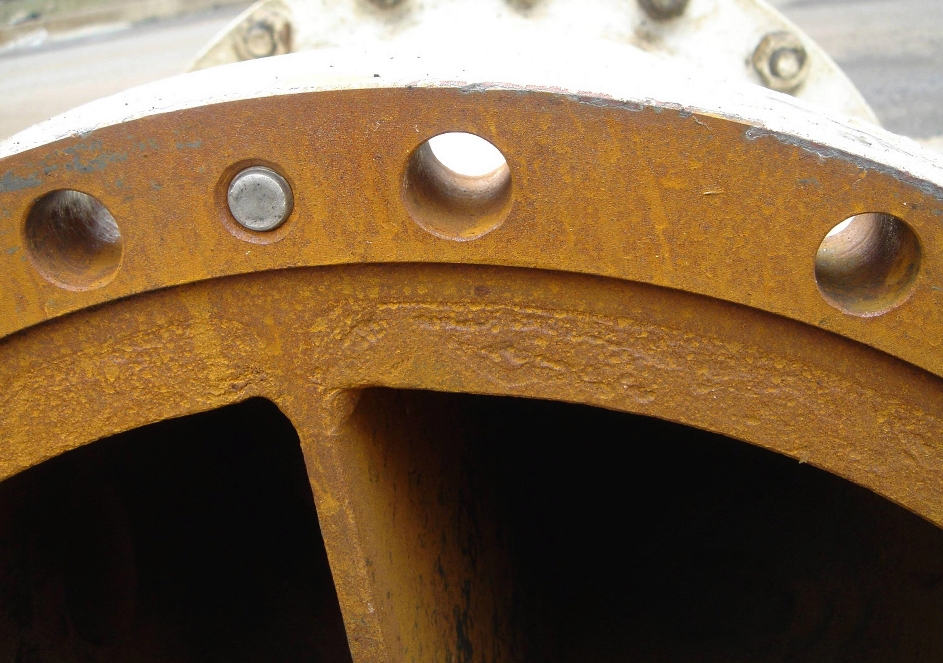
Figure 1: Pitted flange with steam cuts. Photo courtesy of Slade Inc.


Imperfections on flange faces happen. With regular maintenance and removing old, stuck-on gasket\debris, flanges with scratches, pits, dents and dings are a common site in many a plant. With more and more companies adopting low emissions business practices, can damaged flange surfaces seal to meet environmental compliance?


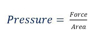
In the fluid sealing world, we know that flange surface is directly related to sealability and sealability is directly related to environmental compliance. As 85% of all known flange gasket failures are installation related, installers must take extra care when sealing damaged flange faces. Acknowledging the importance of proper gasket installation, we’ve compiled a list of 10 steps and considerations for diagnosing and overcoming flange damage.


10 Steps to Sealing Damaged Flange Surfaces


    1. 1. Get an updated copy of ASME PCC-1

      ASME PCC-1 is unarguably the post-construction code bible of bolted flange joint assemblies (BFJA) in North America and following their published guidelines is best practice for bolting assembly procedures. A big benefit in using PCC-1 when sealing damaged flange faces is that it addresses the issue of working with imperfect flange faces and determines permissible amounts of damage that can still work as part of a BFJA and maintain an effective seal. Keep an eye out for updated versions of PCC-1 as fugitive emissions regulations become stricter.


  1. 2. Understand how a gasket & flange work together as part of a BFJA
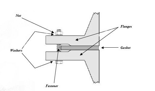
Figure 2: Bolted Joint Flange Assembly. Photo: Guidelines for Safe Seal Usage, Flanges and Gaskets. ESA/FSA Publication No. 009/98


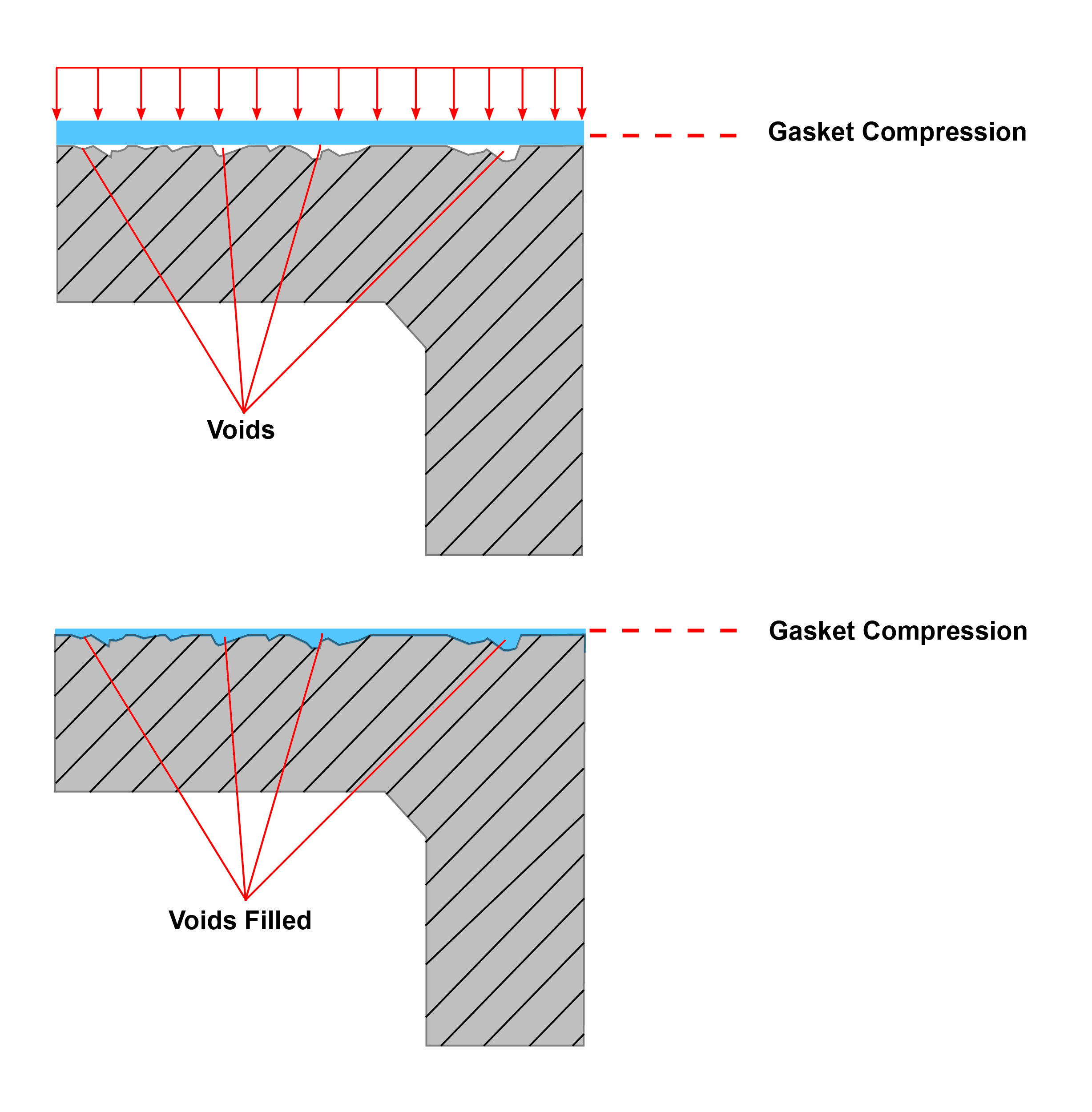
The gasket is meant to create and maintain a static seal between two stationary, imperfect surfaces, containing a variety of liquids or gases under various service conditions. The surfaces or flanges must significantly compress the gasket to ensure a tight seal that has uniform pressure across it, despite any physical damage, like pits or dents. Mating flanges connected by a sealing device have serrations (roughness) on the faces that are meant to “bite” into the gasket material, effectively holding the gasket in place as it is compressed between the two flanges. As the compression happens, forces try to push the gasket material outwards. By holding the gasket in place, the installer is able to compress the seal and achieve desired tightness. The hole in the centre of the ring gasket will compress inwards slightly but remain open to allow media to pass through the pipe.


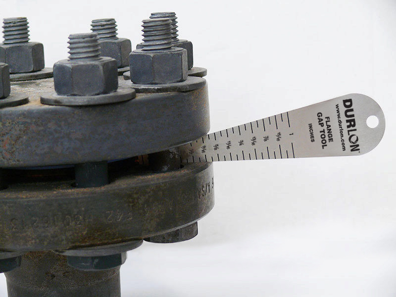
  1. 3. Take apart flange and assess for damage

When replacing gasket material in a BFJA or performing maintenance, pay attention to the flange face. Note any visual defects or damage – marks, scratches, dings or anything that changes the serrations on the flange face that can affect the flange’s ability to “bite” into gasket material. If so, reference PCC-1 for the maximum allowable defect depth and determine if the flange is suitable for service.


  1. 4. Identify a compressible gasket material that can fill imperfections

There is a high probability that damaged flanges could be a factor in BFJA failures. Warped and damaged flanges need to have imperfections filled by a compressible gasket material that can “bounce back” or recover with the flange and prevent leak paths from forming. Because this is widely known, installers believe installing a thicker gasket will solve the problem. However, what they do not take into account is that the thicker the gasket, the more creep will occur and paired with the inevitable decrease of force on the gasket, a gasket failure could result.  The more that creep relaxation occurs, the higher the chance of a blowout.

When using smooth face finishes, such as those usually found in machinery or flanged joints other than pipe flanges, it is important to consider using a thinner gasket to lessen the effects of creep and cold flow. It should be noted, however, that both a thinner gasket and the smooth finish, in and of themselves, require a higher compressive force (i.e. bolt torque) to achieve the seal.

Durlon low emission gaskets for damaged flanges


Durlon PTFE
–compressible gaskets with low creep properties suited to a wide range of service conditions and aggressive chemicals

Durlon ePTFE – highly compressible and versatile biaxially stretched PTFE product that conforms well in worn flanges and can handle a wide range of aggressive chemicals

Durlon ePTFE with metallic core – Durlon Durtec gaskets are virtually uncrushable under recommended loads and are an excellent low-emissions sealing gasket, paired with the conformability of ePTFE on both sides to suit imperfections on flange faces

Durlon SWGs (spiral wound gaskets) – winding density can be altered to allow conformability of SWGs


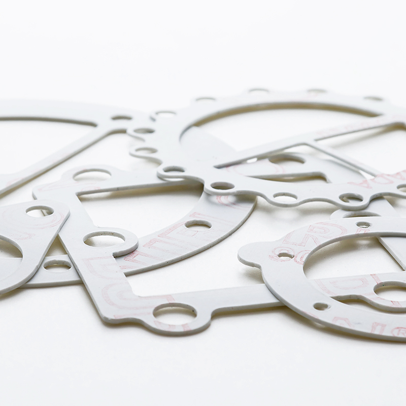
  1. 5. Determine correct thickness

A general rule of thumb for gasket thickness, is that if your flanges are in good condition and under 10” NPS the industry standard is to use 1/16” thickness. For flange sizes 10” NPS and larger the recommended thickness is 1/8”. If a previously installed PTFE gasket is removed and the serrations of the flange protrude through the material, this indicates that perhaps the gasket material being used is too thin and a thicker material should be used. In most industrial sealing applications, 1/32” is the minimum thickness that should be used, depending on the roughness or extent of damage on the flange face.

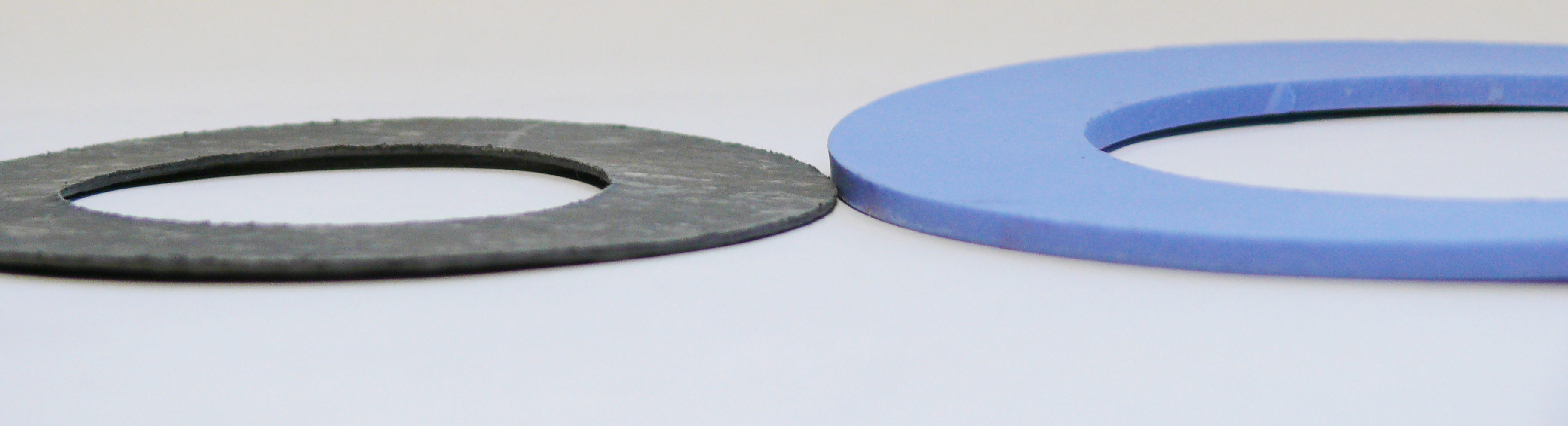
Figure 3: Gasket thicknesses; Left – 1/16″; Right – 1/8″


Note: Regardless of thickness, all of the other standard gasket qualifications must be met including bolt load, chemical resistance, working temperature/pressure ranges, material recovery, systematic thermal cycling, etc.


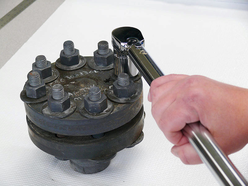
  1. 6. Take extra time installing & use proper torque values

It’s best to take a little extra time when installing a gasket between damaged flanges as improper installation causes approximately 85% of flange gasket failures and can greatly impact plant safety and piping structural integrity. If a single void is left unfilled, the gasket buckles or pinches, a leak path will be created. Be sure the reference the correct torque values by flange size and gasket style/class. Torque values are made readily available by the gasket manufacturer; Durlon torque values can be found on pages 49-53 of the Durlon Gasket Manual.


  1. 7. Add extra passes to bolting “star pattern” in assembly procedure

As an installer begins incremental tightening with the standard “star pattern” bolting assembly, additional passes will ensure the gasket is flat against the flange face. Concentration points forming over pits and marks will increase stress in those areas and possibly crush the gasket in certain places. Extra passes are especially important on worn flanges when serrations don’t “bite” into the gasket and hold it in place. Download a printable Bolt Tightening Worksheet here.


  1. 8. Re-torque

The gasket will inevitably relax, with the majority of creep-relaxation happening between 4-20 hours after the initial installation and must be re-torqued. This is a step that is frequently missed in many day-to-day gasket installations, in part because downtime is not an option for many. An even bigger issue, is when those installers fire up a system right away and re-tighten when the system is hot. This is known as hot-torquing and is not recommended. When a soft gasket material, such as compressed non-asbestos is hot-torqued, the material can crack as it becomes brittle when elastomer based material comes into contact with elevated temperatures.


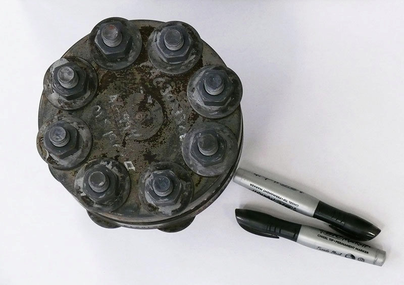
  1. 9. Keep a record of damaged flanges and record leak rates

Keep a detailed record of which flanges in your systems are damaged, so that the same installation procedure can be used.


  1. 10. Replace gaskets or flanges when necessary

In many cases, an imperfect flange won’t be cut off and replaced, but when sealing with environmental compliance in mind, it is best to ensure that leaks are properly identified, recorded and dealt with. In some cases, this means replacing gaskets more frequently, especially if stress concentrators over dents/scratches are causing issues. It is best practice to not re-use gaskets unless direct application and user experience suggests it is safe to do so.


Main Takeaways


Slowing down and properly assembling a flange gasket connection can help companies meet environmental mandates by reducing emissions in BFJA’s. Be sure to properly assess physical flange damage on a flange surface and reference PCC-1. The imperfections seen may be well within the recommended guidelines for use by ASME. If you do have some damage to contend with, consider using a thicker, more compressible gasket material to fill imperfections, effectively preventing leak paths. Become familiar with proper bolt-up procedures and understand how much compression is needed if the switch is made to a thicker, softer material. Avoid firing up any systems immediately after installation and observe and record how the new BJFA performs compared to others.

All Steamed Up – DFT Check Valves for Industrial Steam, Water & HVAC

November 14, 2016

By: Bruce Ellis, Inside Sales


It’s fall and for some, still warm – but it won’t be long until another heating season begins. Some facilities are already seeing the restart of boilers, and so, I’ve decided to address a cold weather issue that often arises with industrial steam and water boilers this time of year: they don’t start. Is there anything worse than a service call at 3 AM in January when the temperatures outside drop to -20°C? Once you have eliminated each component in your boiler as a possible culprit to boiler failure and it comes down to a check valve sticking open or closed in your system, it’s time for a replacement.

Each boiler is unique in the way it is designed and your choice in replacement will be somewhat dependent on the specifications your system requires. Whether you have a liquid, gas or steam boiler, this introduction to DFT Inc.’s three most common check valves for HVAC service is sure to get you warmed up to a replacement valve.

Note: DFT also manufactures check valves for use in large industrial boiler systems. A complete guide can be found here.


BASIC CHECK VALVE

Basic-Check-(1)

This proven check valve is suitable for a wide range of applications and is extremely versatile due to its ability to work at various pressures and temperatures. The Basic Check Valve can be made in different grades of stainless steel and is available from ¼” – 2 1/2” line sizes. The basic check can be used in installations requiring a CWP of 450-6,000 psi. DFT also manufactures the Basic Check with higher cracking pressures, from 2-40 psi. While the Basic Check is versatile, be sure to reference DFT Inc.’s full Catalogue for certain restrictions.


SCV CHECK VALVE

scv check valve canada

The most common check valve for use in steam applications, the SCV is also commonly used with liquid and gas. It uses the same trim as the Basic Check, in a durable body made of either 316 stainless steel, Alloy 20 or Hastelloy alloys with either FNPT or socket end welds. DFT SCV’s are available for ½”-3” pipe sizes and either 750 or 3,600 CWP. The SCV-R (Restrictor Check) is designed for higher cracking pressures than the standard SCV check valve. For a more simplified and flanged version of the SCV check valve, available in ASME Class 150 and 300, see DFT’s DLC check valve.


FBC CHECK VALVE

fbc check valve canada

If you have an existing system with limited space – check this little space-saver out. The FBC “insert wafer” check valve is designed to be installed between two flanges and uses the same proven technology as the Basic Check valve. Though small, the FBC is made to last with stainless steel construction and a well-protected spring, not to mention the FBC can withstand temperatures up to 232°C (450°F). The FBC check valve works with schedule 40 pipe in the most common sizes 1”-4”, pressure class 150/300.


DFT Check Valves Used Extensively in HVAC

The simplicity and durability of DFT Valves has been proven since the original design dates back to the 1940’s and remains unchanged to this day. The non-slam, spring-assisted design prevents  reverse flow and virtually eliminates water hammer in your system. All of DFT’s check valves are capable of water-tight shutoff, are easy to maintain, can be installed in any direction and are built to last. Our distributors and end-users tell us that “they last too long” and regularly comment on their unsurpassed design and efficiency. If you would like to learn more about DFT check valves for industrial steam, water or HVAC, let us know, we’re here to help.


Additional Resources

Design for Flexibility: Key Considerations to Make When Designing Fluid or Gas Flow Systems

Check Valve Application Data Sheet

Durlon® 9000N USP Class VI Certified

Belleville, Ontario – September 29, 2016

Durlon 9000NTriangle Fluid Controls Ltd. (TFC) the manufacturer of Durlon® Sealing Solutions, is proud to announce that the sanitary “white” version of its flagship product, Durlon® 9000N, has been successfully tested and certified to USP Class VI standards for use in the in the pharmaceutical and biotechnology industries. USP (short for United States Pharmacopeia) Class VI is a series of biological tests, requiring a product to show minimal to zero levels of toxicity, making it a suitable gasket material for use in medical devices and other applications where a ‘hygienic’ material is required.

Like the rest of Durlon’s PTFE material, Durlon® 9000N is FDA compliant, making it suitable for use in the pharmaceutical, chemical, food and beverage, and biotechnology industries. Offering USP certification among the Durlon® line of products, allows TFC to better meet the unique needs of its customers who span across a wide range of industries. For more information about Durlon® 9000N, please contact Triangle Fluid Controls Ltd.® at 1-866-537-1133, or info@trianglefluid.com.

Technical Documentation: Durlon® 9000N


Yet Another Promotion Announcement at Triangle Fluid Controls!

Congratulations to Damon Wright, who has been promoted as TFC’s newly established Manufacturing Manager, announced August 17th, 2016.  The former Warehouse Technician joined the company in 2013, and quickly proved himself an asset to the global gasket manufacturer. “Damon has accepted any and all challenges thrown his way and has excelled at completing them. He’s a key contributor to TFC’s team and is greatly respected among our staff,” says Mike Boyd, TFC Plant Manager, who will in October transition to General Manager of TFC. Damon’s new responsibilities will include overseeing and controlling all aspects of plant production operations including costs, efficiencies, hiring, and improving on processes and procedures in order to meet organizational goals and consumer demand.


manufacturing manager

Ryan Kelly Winner of Randy McKay Sales Award of Merit

Belleville, Ontario – July 28, 2016

award


Triangle Fluid Controls (TFC) is pleased to award the 2016 Randy McKay Sales Award of Merit to Ryan Kelly, in recognition for his outstanding sales performance with TFC. The award was given to TFC’s Regional Sales Manager (RSM) whose territory had the largest year-over-year sales increase from 2015 – 2016 and was presented July 28 at TFC’s headquarters in Belleville, Ontario. “We are extremely pleased to award Ryan Kelly with the first ever Randy McKay Award of Merit,” said TFC’s President, Mike Shorts. “Over his short time with us, Ryan has showed immense passion and dedication to our team that has not only seen revenue growth in new markets for TFC but would make the award’s namesake proud.”

The award, created in memory of the late Randy McKay, TFC’s Central Canada RSM, was created by Shorts as a means of paying homage to his former employee. “Randy did a lot for TFC, was a stand-up individual, and somebody that I personally, learned a lot about sales from. After Randy’s passing in 2015, I knew I wanted to create an award in his memory and present it to his family.”

Also in attendance at the award ceremony, was Randy’s son Brock, representing the McKay family. Brock was also awarded a glass sculpture on behalf of TFC, for his father’s dedication to the company. “This place [TFC] meant a lot to him. It was inspiring to see someone who had such a passion for what they did,” remembered Brock.

The award included two pieces: an engraved glass plaque and hand blown glass sculpture made similar in shape, style, and colouring to TFC’s company logo. A second plaque will hang in TFC’s lobby with each year’s winner added to it. The making of the pieces, commissioned by a local glass blower in Prince Edward County, was completely documented and can be found posted online on TFC’s social media channels or by clicking here.


Can Low Gasket Load Applications Meet Upcoming Fugitive Emissions Requirements?

July 19, 2016

By: Chett Norton, C.E.T


Fugitive emissions are a red hot topic right now – and for good reason. With ever-increasing environmental awareness, leakage and how to prevent and reduce leaks should be on everyone’s mind. As a gasket manufacturer, it is Triangle Fluid Controls job to design, develop and educate end users on products that can help them meet upcoming low emission regulations.

Common class 150# flanges are well known as a stubborn culprit when trying to seal flanged connections – particularly 3” and 8” lines sizes.  In the case of 150# flange design, an installer cannot apply enough load to the gasket due to either bolting, flange or material constraints. Another consideration is that with full face (FF) gaskets, you are trying to seal about 2-3 times the area of a ring gasket for raised-face (RF) flanges. You might ask,


“If I can’t apply more load to the gasket, how can I increase gasket load stress?”


Although it is case-by-case scenario, you have two options:


1) Reduce gasket sealing area

2) Use a controlled swell gasket material to intensify gasket stress after installation

Continue reading to determine the best option for your application.


Option 1: Reducing Gasket Area

pressure

Reducing the gasket area is extremely effective and usually one of the easiest ways to increase gasket load, when not enough load can be applied to the gasket. Remember that Pressure= Force/Area, so if we can decrease the area, the pressure (in this case the seating stress) will increase. Specifically, the Durlon RCA (Reduced Contact Area) are designed based on this concept. This type of gasket is fairly unique, even though they reduce gasket area so that the gasket stress is increased. Durlon RCA type gaskets are ideal for full face (FF) flanges and FRP piping that require a tight seal, however, they cannot handle high bolt loads generally required for fugitive emissions or critical sealing applications. The skeleton of the RCA gasket resembles that of a full face (FF) one, except a large portion of the non-critical gasket area is removed for optimal sealing performance.

Front View - FF vs RCA

Option 2: Controlled Swell Gasket Material


In cases where the gasket area is already minimal and cannot be changed by design, or if reducing the gasket area simply isn’t enough, selecting a controlled swell material is a great option. These types of material really shine in low load applications that involve oil and water. Once the gasket is installed, the material swells when it makes contact with oils, fuel or water, which increases gasket thickness. As the material begins to “swell”, the gasket starts to expand, exerting force in both directions, against the flanges. Imagine a Belleville washer being compressed: by design, it applies force in the opposite direction, over the entire gasket-media contact zone and not just the fastener point-load zone. In theory, this is what a controlled swell material is doing. Durlon DuraSwellTM 7760 is a prime example of how choosing a high performance sealing material can negate less than ideal gasket sealing loads and still achieve a tight low to zero emissions seal.

Model


Conclusion


So, can low stress sealing applications meet fugitive emissions requirements? My answer is absolutely. As always, I recommend contacting your gasket manufacturer and providing all of the necessary application details. This will allow a specialist to recommend the proper material and installation methods to ensure the best performing sealing device for your specific needs.


Until next time, stay safe out there, and keep the fluid between the pipes!

– TFC GasketGuru


Additional Resources

Request A Quote

New Durlon® Flange Isolation and Sealing Kits

Durlon® introduces fresh products with tighter sealing capabilities at low pressures that can actually help to protect your industrial system.


Durlon® Sealing Solutions, a leading name in premium PTFE and semi-metallic gaskets, introduced its newest line of sealing technology, dubbed “Durlon® iGuard™” Flange Isolation and Sealing Kits. Conveniently packaged to contain all necessary components to tightly seal, electrically isolate, and effectively control corrosion of mating metallic parts, the end result is a greatly reduced risk of leakage or system failure in severe services such as gas, acids and other aggressive chemicals or media, ranging from cryogenic to high temperatures.


Each kit consists of a gasket, isolating and backing washers, as well as isolating bolt/stud sleeves. Gasket selection can be made from a wide variety of materials to best suit the sealing and performance needs of each application. In gaskets with phenolic or glass carrier rings, a “double-ogee” sealing element provides a reliably concentrated unit load on the flanges using the lowest torqueing conditions possible. Gaskets are available in four different flange facing types and are able to meet all international piping sizes and dimensional standards.

Particularly useful for industry professionals in the Oil & Gas, Chemical, Water/Wastewater and other process industries, the user simply lays the sealing element on the flange face. As the sealing element is compressed against the flange, any tiny gaps between the mating flange and sealing element become filled. This movement provides the end user with a tighter seal, despite potentially lower pressures, with the added ability to isolate parts. The tri-directional movement of the sealing element provides better elastic recovery over time, as bolt loads relax and pressure/temperature cycles occur.


For more information on Durlon® gasket materials available for the iGuard™ flange isolation and sealing kits, technical documentation, product availability and kit specifications, contact Triangle Fluid Controls Applications Engineering department at tech@trianglefluid.com or visit www.trianglefluid.com.


Check Valves for Reciprocating Compressors

Gas problems? No need to raise a stink!

May 31, 2016
By: Bruce Ellis, Inside Sales


If you work in natural gas processing and refrigeration, chances are you know the demands of storing and transporting gas. Compared to fluid sealing and discharge, the media flow isn’t steady, instead, gas “pulses” (through a pipeline) from a reciprocating compressor. This pulsating flow created by the compressor causes the discharge valves to chatter, and while the sound may not be high on your daily list of concerns, the resulting wear or damage to your check valve and downstream components can eventually lead to costly headaches. With the ever increasing global demand for natural gas, issues with check valves and piping systems after installation of a reciprocating compressor is something we see occurring more frequently.


The problem: an ineffective check valve for gas applications.


With natural gas production set to double by 2017 (U.S Energy Information Administration), producers must ensure that their systems are designed with quality parts. While sourcing quality equipment can be time consuming and result in large up-front costs, having the right parts installed in your system will ensure less time spent on maintenance, downtime, and fewer future costs. Ineffective discharge valves are more likely to create issues and suffer undue wear than using a check valve built with a damped design to control the valve’s moving parts. It’s not unheard of to learn of parts that have broken off of valves, damaging downstream components which may cause system failure.


Built specifically for gas applications, DFT’s PDC check valve is a world-class solution found in oil refineries, gas pipelines, as well as storage and pump stations. Its pulse dampening chamber keeps the disc stable and in place (see below video). The PDC is also self-sizing, meaning it can handle different pressures and flow rates, without creating an issue or suffering undue wear. This flexibility extends the life of the valve. As an added benefit, the PDC can protect downstream equipment from damage that could be attributed to other types of valves if they fail.


The PDC check valve is manufactured to meet industry standards and can be built and tested to meet your company’s specifications. Available in various sizes and pressure classes, it can be manufactured using various metals, and is available with flanged, butt weld, or RTJ ends. If you would like to discuss your design needs, call us toll-free at 1-866-537-1133 or email bruce@trianglefluid.com.


Dimensions:

PDC dimensions

Additional Resources:
DFT Catalogue
Valve Data Sheet

TFC Opens Its Doors!

On March 30th, 2016, Belleville ON gasket manufacturer, Triangle Fluid Controls Ltd. (TFC) offered a facility tour in coordination with Canadian Manufacturers & Exporters (CME), through the SMART Program – a collaboration with Canada’s Federal Economic Development Agency focusing on Ontario manufacturing. The insightful manufacturing tour welcomed members of the local community, industry peers, local policy makers, media and members of the CME to visit TFC, to learn about internal processes, manufacturing procedures, understand TFC’s business model and gain knowledge about reaching and exporting to markets around the globe.

The tour provided a free platform for TFC to openly share knowledge, information and expertise amongst business leaders, community partners as well as how to increase productivity, discuss TFC’s information & communication technologies and better monitor energy management and environmental performance. As Tom Gunsinger, C.E.T and President of Bel-Con Design-Builders Ltd. put it, “I know [the visitors] appreciate the sharing of information amongst peers – it helps everyone to strengthen and support each other instead of being adversarial – it’s great.”

“This [CME tour] allows Bel-Con to open up the doors through TFC to other manufacturers and others in the industry to see exactly what goes on at TFC and in the city of Belleville. TFC is one of Belleville’s hidden gems!” said Alan D. Langabeer, Business Development at Bel-Con Design-Builders Ltd.

Also in attendance was Todd Smith, MPP of Prince Edward-Hastings. “A lot of times you drive through the industrial park and see the buildings, yet have no idea what goes on inside – what the products are; how many people work there; the level of technology that’s involved – this was a good education.”

“It’s always interesting to see how complex every little project is,” he adds. “Knowing that a Belleville company is involved in massive projects around the world is pretty neat and that this type of technology, expertise and manufacturing capabilities are happening right in our own backyard.”

When asked about his thoughts on the facility, Bill Saunders, CEO of the Belleville Chamber of Commerce replied, “I think this is the classic example of a phenomenal success story that’s flown under the radar.  I don’t think the community and policy makers truly understand what happens here, the contribution to the community, the challenges they face and the opportunity to leverage this success with other businesses.”

If you are interested in a tour of Triangle Fluid Controls contact Mike Shorts at mike@trianglefluid.com or call our global headquarters at 1-866-537-1133.


P1040217

Triangle Fluid Controls VP & GM Mike Shorts welcomes visitors of the CME SMART Program tour to TFC.

12891551_1050759994985561_7959754253376217765_o

Laura Pixley from CME & Alan D. Langabeer from Bel-Con Design-Builders pose together before things get underway. Photo: snap’d Quinte.

12916874_1050761084985452_3057898537949311864_o

MPP of Prince Edward-Hastings, Todd Smith poses with TFC VP & GM, Mike Shorts, during the facility tour. Photo: snap’d Quinte.

.


Categories