Low Temperature Gaskets – How Low Can You Go?

June 6, 2019

By: Sylvia Flegg, Marketing Manager

Modern technology often requires rare or ultra-pure materials that can only be handled or obtained within extreme environmental conditions. These same conditions present unique and hazardous difficulties when transporting or utilizing these resources. Resources such as liquid oxygen, nitrogen, or argon; all of which are classified as “industrial gases” are handled well below the normal temperature ranges that every-day liquids exist; ranging as low as -195.8°C (-320.4°F).

As an example, let’s look at argon; an important gas used in Welding, Neon Lights, 3D Printing, and Metal Production, just to name a few. It is far more economical to house and transport argon in its liquid state. However, it must be held at an astonishingly low -185.9°C. Fitting the pipes together and maintaining a seal in a cryogenically engineered system that the liquid argon is housed presents unique difficulties. Argon gas is colourless, odourless, tasteless and can irritate the skin and the eyes on contact, and in its liquid form it can cause frostbite.


Proper Gasket Installation

Many gasket materials can become brittle, crack, shrink, and blow out when exposed to extreme cold – not something you want to happen at any time let alone with a liquid that can freeze you into a meatsicle. So, proper installation is also key! During installation, it is important that all parts are dry, the installation is done at ambient temperature and then re-adjusted with changes in temperature.


Cryogenics

Any mechanical seal that is sealing a product with a temperature below 0 degrees Celsius is given the name “Cryogenic”. Liquefied gases (LNG), such as liquid nitrogen and liquid helium, are used in many cryogenic applications, as well as hydrocarbons with low freezing points, refrigerants and coolants.

When selecting a gasket or sealing material to be used in cryogenic service then it is important that the material can withstand cryogenic temperatures.

Low temperature applications are found across many industries, these include:

  • Chemical
  • Food
  • Pharmaceutical
  • Refrigeration
  • Petroleum
  • Automotive


Durlon® PTFE Gasket Material

A good material that can withstand the frigid cold and remain ductile is required to maintain the seal, and the standard go-to is polytetrafluoroethylene (PTFE). Durlon-9000’s low temperature threshold of -212 degrees centigrade makes it capable of withstanding the hostile environment demanded from handling ultra-cold and this glass filled PTFE is capable of resisting thermal contraction which otherwise might compromise the integrity of the seal.


Conclusion

As with all gasket applications, environmental conditions should be considered in conjunction with the functional requirements of the device. Learn more about our various Durlon PTFE products.

8 Steps to Properly Installing a Gasket

April 11, 2019

By Chett Norton, C.E.T. and Sylvia Flegg, Marketing Manager


Visually examine and clean flanges, bolts, nuts and washers and make sure to replace any defective components, if necessary.


Lubricate bolt threads, nut threads & facing, and washers.


Install new gasket (Do not reuse old gaskets or use multiple gaskets).


Number the bolts in a “cross pattern” sequence according to this diagram. Important: hand-tighten then pre-tighten bolts to 20 ft/lb torque but do not exceed 20% of target torque.


Check gap uniformity using a gap tool, feely gauge or Vernier calipers.


Target torque round #1 – 30% of target torque, Round #2 – 60% of target torque and round #3 – 100% of target torque. It is very important that you check the flange gap around the circumference in several spots between each of these tightening rounds. If the gap is not reasonably uniform, make the appropriate adjustments by selective bolt tightening before proceeding.


Rotational round: to reach 100% of the target torque, use a rotational clockwise tightening sequence starting with bolt 1 for one complete round and continue until no further nut rotation occurs at 100% of the target torque value for any nut.


Final-round: Re-torque within 4-24 hrs at ambient temperature if possible. Consult TFC technical department for hot-torquing procedures, repeat round 4 followed by a rotational round. A large percentage of short-term preload loss occurs within 24 hours after initial tightening this re-torquing round covers this loss and is especially important for PTFE gaskets.


We recommend the use of an installation assembly worksheet with the details of the assembly and installation including the installers signature and date for verification. You can use the TFC worksheet for easy adoption into your bolting installation verification program.


For other specific applications or general procedures, please contact the TFC applications engineer at tech@trianglefluid.com and you can read more about our Gasket Installation Procedures here.

Understanding Gasket Temperature and Pressure Limits

May 14, 2019

By Chett Norton, C.E.T.

When choosing the correct gasket material for a specific application, there are 3 minimum fields that you must understand in order to properly select the correct gasket:

  1. Pressure
  2. Temperature
  3. Media

All 3 of these items are straight forward on their own, however, most gasket applications are not based on 20°C or ambient test conditions in a lab so I will talk about each topic and how they interact with each other. The pressure is normally stated on the technical data sheet and refers to the pressure that the gasket is rated to at ambient temperature, so, for instance, Durlon® 8500 is rated for 1500psig at 20°C. Since soft gaskets are only recommended for both Class 150# & 300#, 1500psi seems adequate, right? Well if at ambient temperature, the max working pressure for a class 300# flange is 740psi for WCB piping/flanges and we used 1.5x this working pressure to cover system pressure tests, it would still only be 1140psig – still below the max allowable for the material. Unfortunately, it is not this simple.

What we sometimes fail to realize is that as the application temperature increases, the materials ability to withstand pressure decreases. Based on this, using a material’s Pressure vs. Temperature chart or referencing the materials PxT number are both quick tools that can be used to help verify if the material you have selected will work for the pressure and temperature conditions of your application. Many material tech sheets feature a “straight-forward” and easy-to-use PxT chart. The chart has a line that shows you a ‘go’ or ‘no-go’ area based on the pressure and temperature of the application for the material. Normally the pressure is listed on the Y-axis and the temperature is listed on the X-axis of the chart. Plotting the point at which these two values intersect will advise whether it is safe to use the material or not. If the point is inside the recommended line, it is generally safe to use, while being outside the line indicates not safe to use or recommends you contact engineering for more information. See the chart below for reference.


A second way to quickly check if the material is suitable for the application, is the PxT number. In some cases, the material-technical data sheet for the gasket material will give you a unit-less PxT number. For instance, Durlon 8500 material has a PxT (Psi x °F) value of 250,000 for 1/8″. Now what you can do is divide this number by either the working pressure or temperature (the number used to divide cannot exceed the max allowable temperature or pressure allowed for the material) and it will give you the maximum allowable of the variable not used. Allow me to give you an example:

Durlon 8500, PxT = 250,000

What is the maximum allowable pressure that the gasket can handle at 400°F?

250,000 / 400°F = 625 psi

Therefore, the maximum pressure the material can be used at 400°F is 625psi.

Additionally, media reactivity is also dependent on temperature. In a lot of cases, a materials chemical resistance at ambient temperature is good; however, at elevated temperature, the chemical is much more reactive and/or aggressive and renders the material not chemically compatible anymore. Therefore, it is very important when verifying chemical resistance, the temperature of the material needs to be taken into consideration besides the concentration of the media itself.

So, remember to verify these 3 items (Pressure, temperature, and media) and you can simplify it further by using the Durlon® iGasketPlus app to help recommend the correct material. So, play it safe, use the app and remember to always “Keep the fluid between the pipes”.

Blaming the Valve

March 4, 2019

By: Bruce Ellis, Inside Sales

In many situations where a system starts to suddenly fail, the valve is the first suspect. This may or may not be true, depending on the issue. If a swing check valve is being used it is important to remember they are inherently noisy, so a quiet swing check is a problem. Whereas a non-slam check valve is designed to operate quietly, so if it becomes noisy, there is a problem.

Here are 3 questions to ask to help diagnose the issue causing system failure:

  1. Did the systems components change?

Simply put, is your pump or compressor working at the same efficiency (flow rate and pressure) as when it was new? Or did something change? It’s a good idea to have a pressure gauge and flow meter installed to monitor the conditions.

  1. Did something foreign enter the system?

Foreign objects sometimes find their way into a system causing damaged components, such as impellers and pistons. These objects can possibly get jammed in a valve, causing it to become stuck in the “open” or “closed” position. This can occur when intake screens become dislodged after repairs have been done, or on new installations. There have been documented occurrences where rocks, pieces of wood and even hand tools have been stuck in valves.

  1. Has there been a change in process conditions?

The media in a process can change. Is it more acidic? Does it contain more particulate? Did the specific gravity change? Any or all of the these will change how a valve operates. Increased acidity can cause failure of the spring and corrosion of the wetted parts. Increased particulate will cause faster wear of all parts and can lead to leaks and failure of a valve and other components in the system. A thicker than normal media will put strain on a pump and can slow the “close time” of a valve.

To help save money and down time, it is highly important to have an inspection and maintenance schedule to keep your system working properly and safely.

It’s all about efficiency!

Download the DFT® Silent Check Valve 6-page Brochure now!

Material Spotlight – PTFE (Polytetrafluoroethylene)

Feb 14, 2019

By: Michael Pawlowski, Laboratory Technologist

From interplanetary deep space missions to sealing the fittings between the faucets and pipes in your kitchen sink, Polytetrafluoroethylene (PTFE) can be found being used in almost every aspect of our daily lives. It was discovered accidentally April 6, 1938 by Dr. Roy J. Plunkett while running experiments utilizing gasses for freon refrigeration. The white waxy substance that had spontaneously polymerised was found to have some remarkable properties. PTFE turned out to be a resin impervious to almost every known solvent with a near frictionless surface which no substance would stick to.

The unique properties of PTFE lend itself well for use in a variety of industrial, manufacturing, and engineering facilities. The superb chemical resistance and tolerance to vast temperature gradients has not only improved the efficiency of many industries but the safety for the employees that work around those conditions as well.

12 ADVANTAGES OF USING PTFE FILLED COMPOUNDS

  • Excellent chemical resistance
  • Wide range of service temperature
  • Excellent dielectric properties
  • Non-stick, low friction
  • No embrittlement or ageing
  • Smooth surface finish can be achieved
  • Non wetting
  • Outstanding corrosion protection
  • Electrical insulation
  • High thermal stability and flame resistance
  • Resistance to weathering
  • Food grade compliancy

5 COMMON GRADES OF PTFE

Virgin PTFE
“Virgin PTFE” (PTFE without a filler) is one of the most chemically inert materials known and is used in many different applications and industries.

Glass Filled PTFE
Virgin PTFE with 20-30% Glass fiber filler which dramatically increases compressive strength and lowers deformation under load.

Bronze Filled PTFE
The addition of Bronze to PTFE gives better dimensional stability and lowers creep, cold flow and wear.

Carbon Filled PTFE
The addition of Carbon Fibre to PTFE increases the compressive strength and wear resistance. It provides good thermal conductivity and low permeability.

Stainless Steel Filled PTFE
The material is extremely hard wearing, has excellent strength and stability under extreme loads and elevated temperatures whilst still retaining the low coefficient of friction of conventional PTFE.

PROCESSING PTFE

Because PTFE is a thermoplastic and due to its high viscosity, it cannot be processed using conventional polymer processing techniques. PTFE is processed by cold shaping and followed by heat treatment (sintering) during which polymer particles fuse to form a solid moulding.

PTFE is highly resistant to corrosion due to its chemical inertness. Unfortunately, that same chemical inertness prevents PTFE from being cross-linked like elastomers and is subject to the phenomenon of cold-flow – otherwise known as “creep”. To reduce and diminish cold-flow, additives are introduced during the preparation of PTFE compounds. Fillers, such as glass fiber found in Durlon® 9000 and 9000N gaskets, not only reduce creep but also maintain chemical inertness against aggressive and caustic chemicals but are still considered safe for use by food, drug and medical services.

Durlon® 9000 & 9000N PTFE SHEETS & GASKETS

Various shapes of inorganic fillers have been homogeneously blended with pure PTFE resins to give Durlon® 9000 its physical and mechanical properties. It is suitable for use in steel flanges and will not exhibit the cold flow problems associated with virgin PTFE or the hardness problems of some other filled PTFE products. It cuts easily and separates cleanly from flanges after use.

Certifications
Durlon® 9000 – API Standard 6FA Fire Test, TA-Luft (VDI 2440), BAM, Pamphlet 95 (Chlorine Institute), FDA Compiant, USP Class VI Certified, ABS-PDA Certified, EC 1935/2004 Compliant, DNV-GL Accreditation, RoHS Reach Declaration

Durlon® 9000NFDA compliant, ABS-PDA Certified, USP Class VI Certified, RoHS Reach Declaration


Durlon® 9000 is made with Teflon™ fluoroplastic. Teflon™ is a trademark of The Chemours Company FC, LLC used under license by Triangle Fluid Controls Ltd.

It’s not me…it’s you!

Jan 31, 2019

By: Chett Norton, C.E.T.

I have had many conversations over the years with end users and installers, and the majority of the time, we realize that it wasn’t the gaskets fault for blowing. I often chuckle to myself wondering how the conversation would go if a gasket could talk to its end user? I think it would be very similar to the stereotypical relationship break-up line, “It’s me…it’s not you” but just the opposite, “It’s not me…it’s you” ‑ gasket talking to the end user.

Gasket failures are far too common and in a lot of cases can be categorized into 4 main categories – as this poll explains that was conducted by the FSA on 100 gasket failures. They determined the root cause of the failure causes as:

  • Under Compression (68%)
  • Over Compression (14%)
  • Wrong Product Used (14%)
  • Other (4%)

Under Compression can be caused by not tightening the bolt enough to apply the correct load on the gasket due to manual tightening or friction that is unaccounted for or possibly due to gasket relaxation. As you begin to tighten the material it will start to “creep” due to the compressive load being applied. As the gasket thickness decreases, the originally applied load on the bolts will lessen. This is due to the thickness change resulting in a lower gasket stress or compression and can cause a leak due to permeation through the gasket or tangential between the gasket and the flange sealing surface. Additionally, unloading of the gasket can occur due to temperature or pressure cycling which can have the same effect.

Over Compression is caused by too much load on the gasket. This can be caused by not using the correct torque value or perhaps using a tightening tool that you cannot measure the torque, for example an impact gun or cheater bar extension. Over compression reduces the contact area of the gasket and crushes the gasket towards the ID allowing fluid to penetrate the gasket ID thus leading to deterioration of the gasket, damaged flanges and can result in leakage or gasket failure ‑ a huge problem.

When Wrong Product is used, it can become a serious safety issue. The material selected must be capable for the temperature, pressure and media that it is being installed into. If the gasket material is not rated for either the pressure or temperature of the application, this can cause very serious issues such as worker injury or plant down time. Additionally, the gasket must be chemically compatible with the media or the chemical can attack the gasket; causing it to prematurely break down which may cause leakage or even failure.

And lastly, the Other category could be several things, such as using the incorrect gasket size, poor method of cutting, or quite simply, it is somewhat of anomaly and couldn’t be grouped into one of the three categories above.

The good news is, 96% of the above listed failures can be eliminated as they are in YOUR control! By following these few points, you can ensure that your gasket doesn’t have to give you “The Talk”.

  • Pick the correct material, verify the pressure, temperature and media that you will be installing the gasket into.
  • Use the proper tightening procedure noted in ASME PCCC-1.
  • Lubrication is key, friction is robbing and can account from more than 50% of the required torque.
  • Always use the manufacturers recommended torque values. If you are unsure, give them a call as they will be happy you did.
  • Use a proper tightening tool, such as torque wrench.
  • Gasket creep and bolt relaxation happens, be sure to eliminate this by always remembering to re-torque within 4-24 hrs.

So, the next time you have a gasket related issue, check to make sure it wasn’t due to one of the reasons mentioned above and remember to think to yourself WWTGGDWhat Would The Gasket Guru Do?

Until next time, keep the fluid between the pipes!

At Triangle Fluid Controls Ltd., we provide Gasket Installation Training to help prevent lost production time, to decrease maintenance costs, eliminate fines and to help ease your health and safety concerns.

2017 Randy McKay Sales Award goes to…..

Triangle Fluid Controls (TFC) is pleased to award the 2017 Randy McKay Sales Award of Merit to Ryan Kelly in recognition for his outstanding sales performance with TFC. The award is given to TFC’s Regional Sales Manager (RSM) whose territory had the largest year-over-year sales increase from 2016 – 2017 and was presented August 23rd, 2018 at TFC’s headquarters in Belleville, Ontario. “I am extremely proud to present this award to Ryan Kelly for the second time in 3 years.” said TFC’s General Manager, Mike Boyd. “Ryan joined TFC in 2015 and has demonstrated a high level of energy and commitment to drive sales growth in Ontario and Manitoba. Given Ryan’s passion for his work, I am very excited to see what the future holds for Ryan and his sales territory”.

The award, created in memory of the late Randy McKay, TFC’s Central Canada RSM, was created by TFC President Mike Shorts, as a means of paying homage to the former TFC employee. “Randy did a lot for TFC, was a stand-up individual, and somebody that I personally, learned a lot about sales from. After Randy’s passing in 2015, I knew I wanted to create an award in his memory.”

The award includes two pieces: an engraved glass plaque and hand-blown glass sculpture made in a similar shape, style, and colouring to TFC’s company logo. The glass plaque will hang in TFC’s lobby with each year’s winner added to it. The making of the pieces, commissioned by a local glass blower in Wellington, Prince Edward County, and was completely documented and can be found posted online on TFC’s social media channels or by clicking here.

Sealing for Extreme Cold: Best Practices for Static Seals

As published in Pumps & Systems Magazine, July 2018

Co-written By: Chett Norton, C.E.T.


Flexible graphite and PTFE are commonly used in cryogenic sealing. Natural gas popularity is growing exponentially because of its low cost, low risk to transport and store, and its status as one of the cleanest burning fossil fuels. With increasing global pressure to reduce greenhouse gas emissions, the need to meet growing energy demands while reducing these emissions is more important than ever.

Click here to read entire article.

Congratulations Triangle Fluid Controls on a successful audit!

Triangle Fluid Controls Ltd. Official Listing for Standard:  ISO 9001:2015

We have official confirmation of our company’s management systems Certificate of Registration and we are now listed under NSF’s certified products and services.

This certification accomplishment positions us among the best in our industry for fulfilling the ISO requirements and represents a major investment for our organization.


Sanitary Valves – keeping it clean!

April 26, 2018

By: Bruce Ellis, Inside Sales and Sylvia Flegg, Marketing Manager


There is an ever-increasing demand for dependability, efficiency and energy savings when selecting valves – as it needs to be the correct one! And a function that is often overlooked is the valve’s ability to minimize energy consumption.


Principles of Operation

An essential element in the design of pumping systems is the proper selection of the pump discharge check valve, whose purpose is to automatically open to allow forward flow and automatically return to the closed position to prevent reverse flow when the pump is not in operation.

Check valves are generally made up of plastic or metal. In most sanitary applications you will find the composition of the valve being 316L stainless steel and are CIP (Clean In Place) capable.

Cracking pressure (the minimum upstream pressure at which the valve will operate) is also an important design element of the sanitary check valve.

When selecting a sanitary check valve, you should look at the following criteria:

  • Non-slamming characteristics
    The amount of time it takes for the Check Valve to close and the way in which the disc travels from the open to the closed position.
  • Disk design
    Location is a key factor here.
  • Cost
    Is the initial purchase price competitive? The main things a buyer should consider are system downtime, valve location and cost of parts and labor.
  • Application
    The importance of each selection criteria must be weighed to make an informed selection on the valve best suited for the application.


Our solution – the DFT® DSV® Sanitary Check Valve
The DSV® Sanitary Check Valve is an edge/centre guided disc design valve for applications where CIP designs are required.

They are used mainly in food, chemical & cosmetic factories. These valves are available in horizontal (self-draining) and vertical styles.

The DSV® valve meets USDA and 3A Sanitary Standards and Pharmacopeia (USP Class VI) certifications.


The valve itself is manufactured from 316 stainless steel polished to 25RA and is available polished to 15RA and is fastened with a quick release clamp and elastomeric body seal to permit fast and easy access to the internals. The disc and seat are lapped to provide excellent shutoff.


Features:

  • 1/2” to 4” line size
  • 150 CWP, 108 ASME pressure class
  • Meets 3A Standard 58-01
  • CIP (Clean In Place)
  • Clamped ends
  • 316L body and seat
  • 316 disc, spring & guide assembly
  • 32 Ra internal surface finish (#4 Ground Finish)
  • Electropolished spring (.16 to .66 psig cracking pressure)
  • EPDM body seal (300°F max temp.)
  • Edge-guided disc (1/2” thru 2”)
  • Edge/Center-guided disc (2-1/2”, 3”, 4”)
  • Spring assisted silent closing, non-slam
  • Tight shutoff – lapped disc & seat
  • Horizontal or vertical installation


Options:

  • 15 Ra internal finish
  • Tuf-Flex® or Viton® body seal
  • Straight thru inline or offset inlet/outlet


Download the DFT® Silent Check Valve 6-page Brochure now!

8 Gasket Myths – Debunked

March 13, 2018

By: Chett Norton, C.E.T.


As a gasket application’s engineer, I spend a lot of time speaking with people on the phone or in person on site discussing gaskets. Whether it is material selection, installation or trouble-shooting gasket failures, there are many common things I hear people talk or ask about. So, this month I am writing to try and clear the air and help shed some truth on common things that are either thought to be true or practiced in field.


1. Thicker gasket material is better

People generally request thicker material due to an excessive gap or misaligned flanges. They think that the thicker material will fill the void; however, what they may not be aware of is creep/relaxation. Gasket creep/relaxation is somewhat linear (depending on the material) and the amount of material creep increased with gasket thickness. Want less creep, go thin or go home! Also, things such as torque retention, higher blow-out resistance and leakage (through gasket permeation) are much better with thinner materials.


2. Gasket colours indicate the materials are the same

”I’ve always used a blue gasket, so I need a blue gasket” is a common phrase heard time and time again. Gasket colour is generally meaningless. But in some cases, competitors may choose the same colour for their entire product line. So, to be sure, instead of asking for a specific colour, verify the pressure, temperature and media so that the proper material will be selected for your application.


3. Torque values are the same for all gasket materials

All torque values are not the same. Firstly, when looking at torque charts please be sure to read the fine print to verify bolting material, % of bolt yield used, K-Factor used and the maximum allowed compression for each material. For most soft gaskets, the maximum gasket compression is 15,000psi, however for semi-metallic gaskets like SWG’s and Kammprofile’s the maximum compression is more like 20,000-30,000 psi so there is good chance you could possibly crush the gasket if you use an incorrect value.


4. Leaking gaskets just need to be retightened

If a gasket is leaking, do not retighten. Particularly with soft gasket materials, hot torqueing is very dangerous. Once compressed gaskets reach an elevated temperature they can become brittle and further tightening can cause the gasket to crack. This can further increase the leak or even worse, cause a gasket blow out! If a gasket is leaking, it should be replaced!


5. All gaskets are made the same and perform the same

Not true. There are many types of methods for the manufacturing of sheet materials such as the calendar method, skived method and even the beater add which all give the material different properties. The properties shown on gasket technical data sheets are for QC purposes and allow you to somewhat compare “apples to apples” however they do not actually give you performance data but are merely indicators on how they may perform in certain applications. There are some tests out there like the FSA Steam test which are representative data on how the product will perform in steam applications. There are others for specific properties so be sure you are understanding the correct test values and how they will benefit or affect your sealing application. And you may want to use the materials ASTM F104 line call to truly compare gasket materials because it is the preferred method to ensure you are on a level playing field.


6. Grease or lubricant is a good way to hold a gasket in place during the installation process

Getting a gasket into position during an installation can be tricky, so sometimes people use a dab of grease or lube on the gasket to get it to stick to the sealing face during bolt up. This is not a good idea for two reasons: the grease can chemically attack the gasket material and it also lubricates the sealing face which allows the gasket to be pushed out easier by the system pressure. Now remember, we are trying to compress the gasket enough to fill the flange serrations and have them “bite into” the gasket to resist being pushed out by the system pressure. Putting grease on the gasket negates what we are trying to achieve…..so don’t do it!


7. Softer materials seal better

Firmness is also referred to as the materials ability to resist flow. Softer materials are not necessarily better, but they are good for applications where the material needs to confirm to worn flanges or uneven flanges. It is quite common for the material to have more creep when softer, so this may not be a desirable trade off when choosing the material. For higher temperature and higher pressure applications, material hardness and sealing surface finish need to be strongly considered.


8. Gasket installation procedure doesn’t affect sealing performance

Gasket installation is the most influential factor that affects sealing performance. If you do not install the gasket using a correct method such as the Legacy Method (see figure 1), an alternative method listed in ASME PCC-1, Appendix F or the method recommended from the manufacturer, you run the risk of not getting the most out of your gasket. Using a proper installation method helps the installer bring the flanges together in parallel which lessens the risk or crushing the gasket or unevenly loading the gasket which can cause leaks. Furthermore, it ensures that the load applied to the gasket (via torqueing) is correct and consistent which is important in gasket sealing performance.


Figure 1. Legacy Method Bolt Tightening Pattern


So, there you have it, hopefully this sheds some light on some common myth’s when selecting or installing gaskets. If you have one that wasn’t covered, feel free to drop me a line at tech@trianglefluid.com or @TFCGasketguru on twitter and we will get you on your way to better sealing!

Until next time, keep the fluid between the pipes.

Download the Durlon® Gasket Manual now!

How Gaskets are Measured

February 23, 2018

By: Chett Norton, C.E.T. and Sylvia Flegg, Marketing Manager

Gaskets come in all shapes and sizes: round, oval, rectangular etc. Accurate measurement size is important because it ensures that the gasket will fit properly and will not get in the way of the installation. Additionally, measurement is managed by QC, assuring that the gasket will comply with either the customer specifications or tolerances given by specific cut gaskets standards such as ASME B16.21 & EN1514-1. To help illustrate some of these points I am going to give you two specific examples of what to measure and what to avoid doing.


Ring gaskets are quite simple to measure because you only need to verify two measurements: Inside Diameter (ID) and Outside Diameter (OD). Ring gaskets are generally used in raised face (RF) flanges as the gasket is centered inside the bolts. Generally, it is not recommended to use ring gaskets in full face flanges as they are thinner and more fragile. Since the ring gasket OD does not line up to the edge of the flange, any bending of the flange (flange rotation) caused by tightening bolts could result in severe damage.

Full face gaskets are a bit more difficult to measure because there are five things that you need to verify correctly: Inside Diameter (ID), Outside Diameter (OD), Bolt Circle Diameter (BCD), bolt hole diameter and the number of total bolt holes.


Full face gaskets are commonly found in flat faced flanges but are also occasionally used in raised face (RF) flanges. For ease of use in RF flanges, installers insert the gasket between the two flanges and insert two or more bolts to align the gasket before installation. Although using a full face gasket in a RF flange adds cost to the installation, this minimizes the gasket from being improperly centered and makes the installation process easier.

Measurement Methods

The most common hand tool used for measurement is a tape measure or ruler. Either can easily allow the person to check the ID and OD of the gasket by visually verifying the dimensional increments on the tool. Bolt holes and the bolt circle diameter of a gasket are a little trickier; however consistent measurements can be obtained with a little practice. These types of measurement tools should not be used when high precision measurements are required.

Vernier Calipers are another handheld tool that are much more accurate than rulers and tape measures. The digital read allows measurements to as low as 0.001” increments. Vernier calipers come in various size ranges, so if you have range of gaskets sizes to measure, there is a good chance that may need two or three sets to cover the full range of sizes that you need.

The two methods I have listed above both have one major disadvantage in common when it comes to measurement – human error. When trying to measure gaskets, they can become “egg shaped” or oval. The simple way to eliminate this error is to use a jig or a pass/fail fixture that allows you to insert the gasket without having to physically measure it. If the gasket fits, it passes and if the gasket does not fit then it is rejected. The down side to this type of fixture is that it can be costly to make and you will need a fixture for each individual gasket size.


So there you have it! I hope this gives you some oversight on what to look for, or consider when determining gasket measurement.

Until next time, keep the fluid between the pipes!

Request a Quote Now!


Common Gasket Cutting Processes – 3 Technologies To Consider

January 25, 2018

By: Chett Norton, C.E.T. and Sylvia Flegg, Marketing Manager

As a manufacturer of gasket material, a common question we are often asked is, “How can you cut this”? It’s a great question that can yield several options based on the knowledge of our experienced gasket engineers to help meet your needs quickly and economically.

When it comes to soft gaskets, there are three main cutting methods with each providing its own pro’s and con’s depending on the gasket requirements. The main considerations for each method are time, quantity, tolerance requirements, material scrap/yield and the quality of cut.
 

Gasket Cutting Processes

1. Manual cutting methods are very common and generally performed in plants for jobs that require custom gaskets to be cut in the field. The material can be cut with a utility knife, scissors or shears, or even by a battery operated device. The dimensional tolerance of hand cut gaskets is based on the person cutting the gaskets, however, realistically the tolerance on most hand cut gaskets would be greater than +/- 3.2mm (1/8”). Additionally, with hand cut gaskets, there is usually more than one scribe or cut mark, which can potentially lead to jagged edges or nicks in the gasket, thus creating a weak point. Manual cutting is somewhat slow and tedious, and tends to result in a higher yield of gasket scrap or waste.


2. A Clicker press is another method that is commonly used in higher production runs. A rolled steel die is made up and then the die is placed on the material and pressed into it by a pneumatic press. The tolerance of the gasket is much higher than manually cutting and the material yield is much better. The process is still done manually, however, the yield of material is based on the user/operator. The process is economical for larger gasket quantities because a die still needs to be made for each size and there is some maintenance involved in sharpening and maintaining the dies. Die cutting is not recommended for larger OD gaskets, or custom sizes that required small quantities.


3. CNC digital cutters utilize a 3-axis cutting head that have either an oscillating head or drag knife that cuts the material. Gasket dimensions are converted to CAD drawing file(s) and then uploaded into the machine to be cut. The big benefits to using these types of cutters are the speed, high level of accuracy and material savings due to being able to nest all the gaskets together for the optimal yield. Additionally, for custom size gaskets there is no die or tooling required just a CAD drawing to upload. Literally the operator can put the material on the table, nest the gaskets desired to cut and hit start and walk away.


We have many custom fabrication capabilities and we’ve seen success with all of these in different materials on our product line. If you don’t produce your own gasket material, one of the most important things you can do is ask your gasket manufacturer how they would recommend you cut the material. It sure beats wasting time and precious material!

Happy Cutting!

Custom Cut Gaskets, made to order. Simply send us your CAD file, detailed drawing or gasket photo and we can manufacture your fully customized gasket design. The end result is a quality gasket, made to your specifications, priced right and shipped in days. Contact Us Now!


Featured Article published in “Environmental Science & Engineering” Magazine

SELECTING PROPER GASKETS FOR WATER TREATMENT FACILITIES INVOLVES MANY CONSIDERATIONS

By Chett Norton, C.E.T

The importance of plant operators and operations in water treatment facilities selecting the right gaskets cannot be overstated. Unfortunately, they are often the last thing that anyone thinks about, and are in most cases considered a commodity item. However, most operators say that it is gaskets that can cause the most “pain” on a day-to-day basis. This means that selecting the right ones is important for process safety, environmental protection, service life, and maintenance and inventory costs.

The National Sanitation Foundation (NSF) has created standards that are intended directly for drinking water and systems that treat and deliver it. NSF/ ANSI 61 standard is based on the health effects of drinking water components.

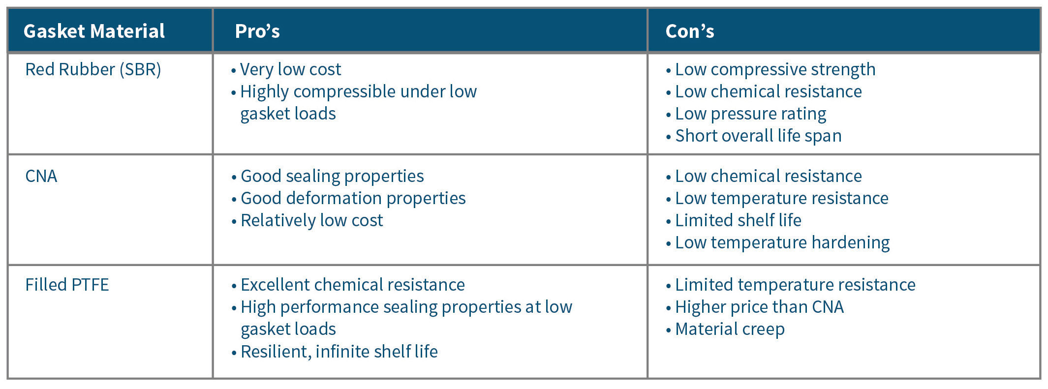
Unfortunately, municipal facilities do not always use NSF 61 approved gasket material. Red rubber, styrene butadiene rubber (SBR), is continually used for potable water applications. But, it is not an ideal gasket material because it is a pure elastomer which naturally degrades over time, because of natural environmental conditions. Red rubber also has a very low compressive strength, generally in the range of 800 psi – 1200 psi, which can result in the material crushing if these values are exceeded.

In most flange pipe connections, the amount of torque applied to the bolting to achieve a minimum bolt stretch of 40% may exceed these values. Failing to stretch the flange bolts to this minimum yield can be problematic because the bolting material is not within its elastic region, and cannot create a “spring like” clamping effect on the flanges. This can result in a leak, or perhaps a blow-out failure.

The chemical resistance of SBR is relatively low against common water treatment chemicals like sodium hypochlorite, caustics, chloramine and others. These chemicals can aggressively attack the red rubber, resulting in a rapidly degraded or deteriorated gasket. When the gasket is chemically attacked, it is susceptible to leaks, failures or perhaps even a gasket blow-out which can seriously harm plant personnel if they are sprayed with these chemicals.

For general plant services that process non-potable water, steam and various forms of waste products, compressed non-asbestos (CNA) gasket material is a good choice because of its good sealing characteristics, ease of cutting and relatively low cost.

CNA gasket material has three main components: fibre (15% – 35%), binder (10% – 20%), filler (50% – 70%). Additionally, there is a small percentage of vulcanizing chemicals which are usually solvent based and used to cure the rubber based binders during manufacturing. Fibre is added to the CNA gasket material to provide increased mechanical properties like tensile and compression, and can include aramid, cellulose, ceramic and glass. The binder is usually composed of an elastomer, namely nitrile, styrene butadiene rubber, or even ethylene propylene diene monomer rubber, which keeps the sheet bound and gives the gasket material added flexibility.

Fillers such as silica, mica, clay or even powdered graphite can be added to help control creep and reduce cold flow. Additionally, using fillers helps reduce the overall cost of the sheet because it consists of 50% – 70% of the total material. When selecting a CNA gasket material for potable water, the user should make sure they use a NSF 61 verified material to ensure that they are not contaminating the water source. Because CNA gasket material contains a rubber component, the material still does have a shelf life. Over time, the rubber will start to break down and deteriorate, based on exposure to environmental conditions.

Due to the rubber component of this type of gasket material, it is not recommended to seal applications that involve acids, or caustics which are used in pH control prior to the clarifying stages or even disinfection chemicals such as sodium hypochlorite (NaClO), 12% solution.

Even polymer-based chemicals used in wastewater treatment, including flocculants, coagulants and defoamers, can cause deterioration in rubber-based gasket materials. Therefore, it is very important to test the chemical resistance of the gasket material used with each chemical and to measure the concentration.

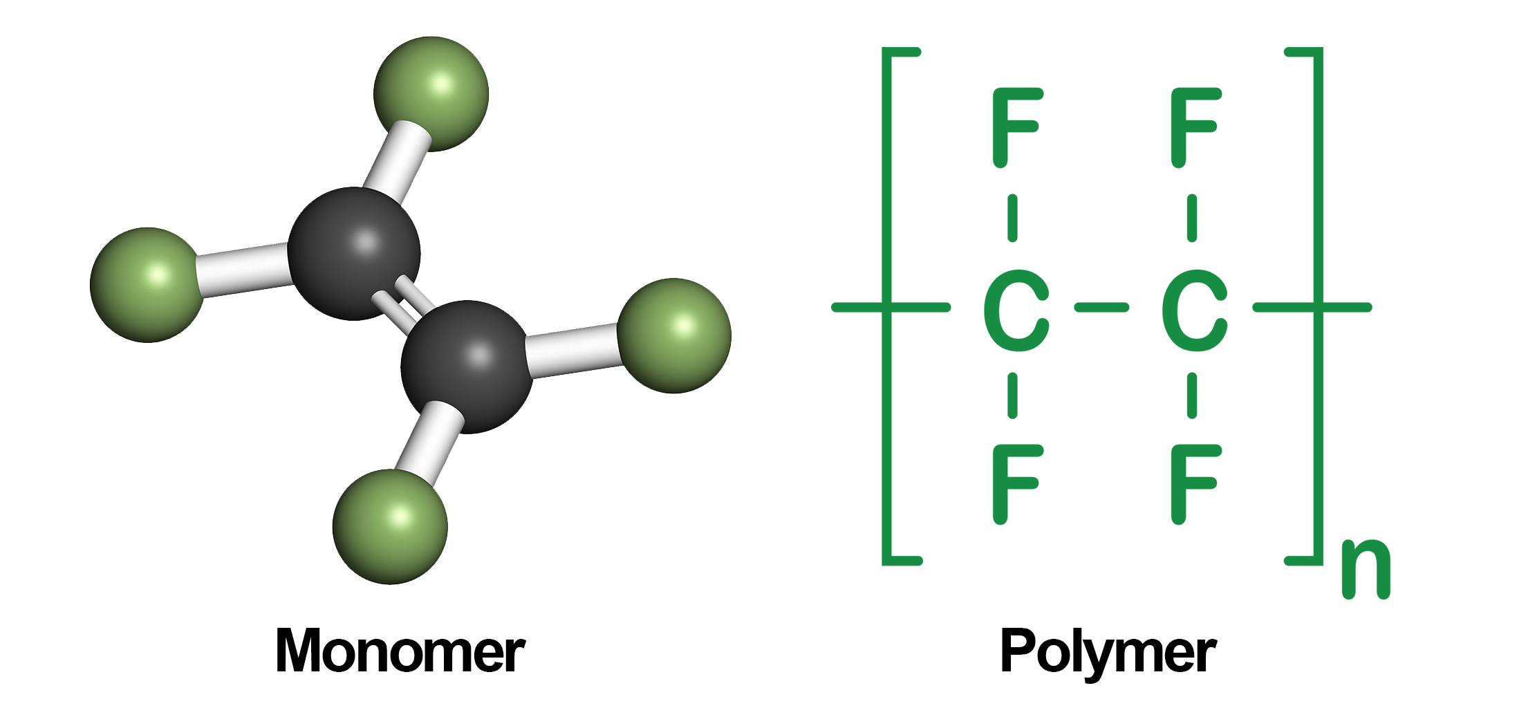
For critical service and chemical applications, filled polytetrafluoroethylene (PTFE) gasket material is an excellent choice because of its in-service longevity, chemical resistance and high sealability.

PTFE has an infinite shelf life; therefore, it does not break down during exposure to environmental conditions. This makes it a superior choice for applications that are not easily accessible or perhaps buried underground. PTFE is also inert to almost every chemical, making it a great choice for chemical applications.

Pure virgin PTFE has high creep/relaxation characteristics, so it is not a good sealing material. To help prevent material creep, gasket manufacturers use engineered filler systems that can consist of glass, barium sulfate and/or carbon.

Filled PTFE seals at a much lower gasket stress than compressed non-asbestos products. However, it can also withstand loads of up to 15,000 psi, which is more than 10 times the compressive strength of red rubber. 75 mm, 200 mm and 300 mm 150# ANSI flanges can be problematic to seal due to the low cross-sectional “bolt area” to gasket “sealing area” ratio. Full face gaskets are also difficult to seal when compared to ring gaskets, due to having two to three times more sealing area. For these applications, filled PTFE is a preferred sealing material.

Full face flanges are generally found on pumps and cast iron 125/250# piping. In many cases, you cannot generate enough gasket compression stress to create an effective seal without damaging the flanges. For these flat face flange applications, reducing the gasket area will help increase the gasket stress. When bolting up the gasket, a reduced contact area gasket made up of filled PTFE, will allow the full face skeleton design to support the entire flat face flange. It will also prevent any damage that may be caused by bending or flange rotation if a ring gasket were to be used.

The application will influence the gasket selection; however, proper gasket installation is equally important. Based on 100 gaskets analyzed and material collected from the members of the Fluid Sealing Association, up to 85% of gasket failures were due to faulty user installation. Sixty-eight percent of the gaskets failed due to under compression, while 14% failed due to over compression.

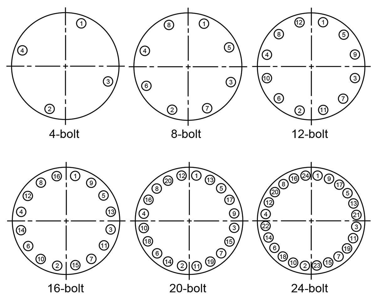
It should be noted that both under and over compression of the gasket can be prevented if installers use a proper tightening method, recommended torque value and a calibrated torque wrench or other tightening device. For proper gasket installation methods, users can reference the ASME PCC-1 post construction guideline for pressure boundary bolted flange joint assembly. Gasket manufacturers provide recommended torque values and installation procedures.

Click here to view other articles from this issue (Dec 2017).

FSA Award of Merit

Triangle Fluid Controls (TFC) proudly congratulates Chett Norton as the recipient of the FSA Award of Merit in recognition of his exceptional technical contributions to the Association and for his efforts to promote the mission of the FSA.

The Award of Merit is presented by the Board of Directors and the Members of the Fluid Sealing Association and was established to recognize distinguished or exceptional service to the FSA by an individual member and granted solely on merit and participation in all activities that support the FSA mission.

Categories