Board of Directors Appoint Mike Boyd, Vice President & General Manager of TFC

June 9, 2020

FOR IMMEDIATE RELEASE

Board of Directors Appoint Mike Boyd, Vice President & General Manager

Triangle Fluid Controls’ (TFC) Board of Directors is pleased to announce the appointment of Mike Boyd as Vice President & General Manager of the company. Mike started with TFC as an Operations Manager in January 2009 for the PTFE gasket manufacturing operations and was promoted to General Manager in October 2016 for the entire company. Under Mike’s leadership and guidance, TFC has continued a prosperous track of top-line and bottom-line growth with improvements in efficiencies, cost control, market expansion and diversity, sales depth, supplier strength, marketing penetration, employee development, and community engagement.

Triangle Fluid Controls is the global manufacturing center of the Durlon® brand of fluid sealing products recognized around the world to solve tough fugitive emissions sealing applications. “Under Mike’s keen eye for operational efficiency improvements and his continuous improvement approach to the business and his professional skills, TFC and Durlon® will continue to be global market contenders for many years to come.” Mike Shorts, President, Triangle Fluid Controls Ltd.

Congratulations Mike on your achievement, your leadership strength, and your dedication to making us a better company!

###


Considerations When Upgrading or Changing Pre-Specified Gaskets

May 13, 2020

By: Samantha Harrison, Lab Testing Technician/QA Assistant

With on-going global changes, most industries in turn, have reflectively looked at making improvements in their choice of gaskets for their particular application needs.


Here is a list of factors that can contribute to changing and/or upgrading a gasket:

  • Change in the process or application
  • Change in environmental regulations (lower emissions)
  • Changes effecting long- or short-term gasket spending
  • Change to a supplier that can provide better service and technical support


Using the ASTM F104 line callout chart can assist with cross-referencing and/or comparing existing gaskets thus improving the material selection process and the transitioning towards the gasket replacement. Most manufactures will complete F104 callout numbers for their products to promote easy comparison. It should be noted that in some cases, the line callout will use the digit ‘9’ which denotes as specified, meaning you will still need to look up the value from the product technical data sheet.


Some gasket properties such as creep relaxation, maximum compression and even material thickness selection can cause a change in the installation procedure and/or required torque value. Each product type is based independently on different equipment and processes using different formulations. Depending on the gasket type selected, the installation parameters can vary, requiring more/less minimum loading in order to establish a leak-free seal. A determination will be established depending on the application changes that have occurred within the system. For example, the addition of new equipment or process changes/improvements. In most cases, this is a factor that is commonly overlooked and not planned. A change in the operating pressure or temperature can affect gasket performance requirements but if properly selected based on design (not operation) the gasket can still fit into existing parameters, and save a lot of headaches down the road.


Here are parameters that need to be considered when changing and/or upgrading a gasket:

  • Temperature
  • Pressure
  • Process fluid
  • Operating conditions (process cycling or vibration)
  • Flange Conditions
  • Service life


It is recommended to always review the published data sheets regarding new gaskets. This will help ensure that the gasket will be able to withstand the conditions where it is intended to be used. Reviewing the pressure-temperature charts will ensure that the gasket will be operating in the safety zone when there is a change in conditions over time.

The following in an example of our Durlon® 9000 PTFE gasket material PxT Chart

“So as you can see, there is a lot more to gasket selection when considering a change or an upgrade…and not as simple as choosing a specific colour!” If you have questions or are unsure, please be sure to contact the manufacturer of the material.

Learn more about our product line of Durlon Gaskets.

More Gasket Guru Training Videos to come!

May 1, 2020

By: Sylvia Flegg, TFC Marketing Manager

Finding a reliable sealing solution has never been easier!

With the past success of our 2019 release of 4 SEALutions videos, we are happy to announce that more will be coming later this year!

This past year we presented a brand new video series, SEALutions, that answers basic fluid sealing questions in 1-2 minute videos. Topics we covered were: Re-Torquing a Bolted Flange, Quality Control Testing for SWG’s, Handling & Shipping of SWG’s and, Gasket Failure Analysis. They can all be viewed here.

SEALution’s stars TFC’s Gasket Guru – QA & Engineering Manager, Chett Norton, a hands-on, tech guy with a plethora of fluid sealing knowledge to share. Chett has over 15 years of experience in fluid sealing and industrial process and is a certified member with the Ontario Association of Certified Engineering Technicians and Technologists (Mechanical Discipline) as well as an active participating member of the Fluid Sealing Association’s Gasket Technical Committee.

Stay up to date with SEALutions by subscribing on our YouTube Channel. In the meantime, you can reach the Guru by e-mailing chett@trianglefluid.com for your fluid sealing needs or if you have any suggestions of topics for future videos.

Press Release – TFC Producing PPE Face Shields for QHC

April 22, 2020

Triangle Fluid Controls Ltd. in production of more than 1,000 face shields to be delivered to front-line health care workers at Quinte Health Care (QHC).

Triangle Fluid Controls Ltd., proudly announced their plan to start production of more than 1,000 Medically Approved Face Shields for QHC, the regional health care
sector. Quinte Health Care provides a wide range of high-quality health care services to 160,000 people living in the 7,000 square kilometer region of Prince Edward and Hastings Counties and the southeast portion of Northumberland County.

Using our manufacturing capabilities and employee involvement, we will be producing the main components for these medically approved Face Shields. Along with TFC’s contributions, we were able to source other required materials from a couple of our suppliers as donations for this combined accomplishment. The cost of the main material; PETG Plastic, is being funded by the employees of Triangle Fluid Controls Ltd. through donations.

“We heard the call for PPE, and as proud Canadians, we knew we had to help. Through donations from our employees and generous partners, we are proud to be able to do our part for front-line health care professionals in our local region.” Mike Boyd, General Manager

Triangle Fluid Controls Ltd. is a market-driven, technology-based company, serving customers throughout the world with innovative sealing products. Based in Belleville, Ontario, we manufacture and distribute filled-PTFE, compressed non-asbestos sheets/gaskets, metallic and semi-metallic gaskets.

Along with TFC’s contributions, we would like to thank Joe Mathew of AM Rubber & Foam for donating the rubber inserts and John Hume of Hume Media Inc for donating the printing of the labels. The cost of the main material; PETG Plastic, is being funded by the employees of Triangle Fluid Controls Ltd. through donations.

Using the ingenuity and collaboration of some of our staff members design skills, we are also going to provide these mask mates – an alternative to attach surgical masks behind the head, protecting ears from the elastic.

Download the Press Release here.

Read article from Quinte News here.

A 360° Look at Check Valve Flow Orientation

April 16, 2020

By: Bruce Ellis, Inside Sales Consultant at Triangle Fluid Controls Ltd.

Check Valve Flow Orientation and Position Explained

As we know, not all styles of check valves are suitable for different flow directions. Pump design or space limitation are important considerations when designing a system that specifies the correct check valve to be used.

Given correct information, DFT axial flow centre guided check valves can be customized to most applications, thus increasing the performance and life span of the components in your system. If we know the media, its specific gravity and system design specifications, pressure, flow rate, temperature etc.; the correct valve can be customized to suit your application.


Horizontal Flow

This is the most common of the flow directions and all check valves. The question then becomes: “How do you choose one valve style over another?” It may be as simple as initial cost or lead-time. This can easily be offset by the advantages centre guided valves have over swing check and dual door designs:

  • virtual elimination of water hammer
  • reliable and less troublesome
  • elimination of costly maintenance and downtime


Vertical Flow (Up)

This installation is commonly used in mine de-watering and sump applications, or where space is at a premium. It is important to remember any foreign matter introduced into the system, such as sand, can settle on the closed valve causing it to not open or close properly. If you are aware of this, modifications can be made to help prevent the problem. Again, since spring assisted axial flow valves don’t require backflow to aid in closing, water hammer is not an issue and the system will work smoother.


Vertical Flow (Down)

This is the most difficult flow direction for check valves to function. This orientation can be found in boiler supply lines and occasionally skid designs that are very space-limited. Some designs, such as swing checks, cannot be used in this situation, as they will open but not close. The spring assisted centre guided valves can be made to operate in this orientation. Given the static head pressure the valve is subjected to, the added spring will allow for proper operation.


In closing, it is important to note that the greater the amount of information given, the easier it is to make an educated buying decision. DFT Check Valves come in different styles, wafer, flanged and NPT (National Pipe Thread), to satisfy most requirements. They are also available in exotic alloys and can be customized to suit most applications.


As the Canadian master distributor for DFT® silent check valves, TFC proudly stands behind these product offerings and it shows from the beginning of our process, to the care taken in packaging and shipping to your door.


For more information please see the helpful resources below from dft-valves.com. We are here to help, so please contact us for any information you require.


You May Also Be Interested In:

E-Book: Design for Flexibility: Key Considerations to Make When Designing Fluid or Gas Flow Systems


DFT Check Valve Catalogue

DFT Valve Data Sheet

DFT Installation & Maintenance Manual

Should I stay? Or should I go?

April 14, 2020

By: Sylvia Flegg, TFC Marketing Manager

Gasket Shelf Life

The shelf life for Durlon® gaskets vary, depending on the material and the length of time it has been stored. All full-sized sheets and rolls of Durlon® materials are fully lot traceable and have the applicable batch number and cure date printed on each sheet. Each material, however, ages differently so here are a few standards we recommend under normal storage conditions:


5 Year Shelf Life

Durlon® Compressed Non-Asbestos (CNA) sheet materials

6 Year Shelf Life

Durlon® HT1000

Unlimited Shelf Life

Durlon® PTFE sheets, Flexible Graphite, Durtec®, Kammprofiles and SWG’s


Storage Conditions

  • Gasket material should be stored in a cool, dry location.
  • Avoid storage of material in direct sunlight or near heaters.
  • Avoid contact with water, oil or chemicals.
  • Gaskets should not be stored so that they become too tightly packed and damaged.


Other Recommendations

  • All dust producing processes such as drilling, grinding and sawing should not be used near gasket materials.
  • Avoid hanging gaskets on pegs or nails as this may cause distortion of the gasket.
  • When stocking the shelves or bins where gasket materials are stored, the material should be rotated by placing the older material first or on top with the newer material behind or under it.
  • All gasket material should be properly identified to guard against misapplication.
  • Consider consolidating materials to 1 or 2 if possible, to prevent using the incorrect gasket usage – for example, Durlon® 9000 or 8500 both feature multi-application usage.


So, referring to some of the above, I like to describe ideal gasket storage similar to how some of us like to vacation – clean of sand, in the shade (out of UV) and laying down…and perhaps with drink in your hand!

What is Ideal Gasket Stress?

March 26, 2020

By: Samantha Harrison, Lab Testing Technician/QA Assistant

Gasket stress is a very important parameter that describes the unit load of a bolted joint surface because each type of gasket material responds differently to gasket stress. Soft and conformable gaskets may seal at low gasket stress where hard metal gasket may require much higher stress. It is always important to contact gasket manufacturers to determine the recommended gasket stress and/or how the gasket will react with the load that is available.

There are 4 aspects to gasket stress


1. Conforming to flange surface

A flange surface will never be perfect. There could be pitting or corrosion that affects the surface, requiring the gasket to have enough compression to form and fill the voids.

2. Block the gaskets material permeability

The gasket needs to be able to block any permeability in the gasket body. The permeability through gaskets are different for each material. The rate of leakage decreases as the compressible load increases. The required stress is dependent on the permissible leakage requirements determine by the end user, such as a T3 tightness level (0.00002 mg/sec/mm-dia).

3. Withstand internal pressure

The gasket needs to be able to withstand internal pressures acting upon it. The minimum compressive stress needs to be high enough to maintain the friction that is needed to keep a gasket from blowing out. This is more common for non-metallic gaskets that has internal pressures that are dependent on friction.

4. Temperature

Temperature is an important factor when determining gasket stress. When temperature is elevated it will cause gasket relaxation and relaxation in the bolt load. When installing the gasket, it needs to have a high enough stress that will compensate for this. Therefore, it is always important to retorque the gasket 4 to 24 hours at ambient temperature after installation.

There are different types of stresses that occur in a system; minimum seating stress, ideal operating stress, minimum operating stress and maximum operating stress specific to a given gasket material. The values for these stresses can be found in ASME PCC-1.

  • Minimum Seating Stress
    Occurs when there is an assumption of little or no pressure for the gasket to be able to conform to the flange.
  • Minimum Operating Stress
    This is dependent on the design pressure of the assembly.
  • Maximum Assembly Gasket Stress
    Is the stress that could damage the integrity of the gasket to affect the ability to maintain a seal.

The target stress to be used will allow for optimal performance and sealability. This will be at a value that is not too high to cause damage to the gasket but at the same time, allow enough load to the gasket.

It is always important to properly install a gasket. If done correctly, with adequate gasket stress and proper procedures, be assured that the gasket is given the best chance for a leak free service life.

Learn more about Gasket Installation Procedures.

Packaging and Handling SWGs

February 28, 2020

By: Samantha Harrison, Lab Testing Technician/QA Assistant

Spiral wound gaskets (SWGS) are a multi-component product that needs to be handled with care to prevent damage to the gasket. So it is very important to take great pride in packaging these SWG’s so that they reach our distributors safely and intact.

Storage

Most gaskets, including SWGs can be used safely after being in storage for years. SWGs should not be exposed to extreme temperatures, humidity, ozone and UV when being stored. These can cause accelerated deterioration of the gasket. Ideally some storage tips are:

  • Store in a cool, dry place
  • Do not expose gasket to excess heat or humidity or extreme fluctuations of heat and humidity
  • Keep gaskets clean and free of mechanical damage
  • Prevent dust and particulate damage
  • Avoid hanging gaskets

Handling

  • Keep gaskets flat or adequately supported to avoid any distortion
  • Extra care should be taken when handling large SWGs greater than 500mm (20”) in diameter
  • For SWGs that are greater than 800mm (32”) we recommend additional hands in order to properly support the gasket
  • Always wear gloves when handling SWGs and do not hold the inner or outer ring only

When handling a SWG it is always important to handle the SWG by the outside of the gasket instead by the center winding of the gasket. When held by the center or winding it could cause the gasket winding to pop…. So, don’t do that!

Packaging

  • When packaging smaller gaskets, it is common to package 10 to 20 gaskets together with spacers attached to help prevent inner ring popping. These spacers can be re-used and cut down when storing or re-shipping smaller stacks of SWG’s.
  • Then the gaskets are shrink-wrapped.
  • Large gaskets 20” in diameter normally come singular and are attached to a piece of cardboard to keep them ridged
  • It is common for the sealing to become dislodged from the centering ring. In most cases they can be reassembled with a little bit of patience.

Watch this short video showing a re-assembled SWG.

Remember that SWGs are made of multiple components and need to be packaged well in boxes. If boxes rattle, the packaging is no good.

What is m and y gasket design constants, and how are they used?

December 3, 2019

By: Samantha Harrison, Lab Testing Technician/QA Assistant


m & y explained

Gaskets are designed to maintain a static seal between two stationary, imperfect surfaces of a mechanical system and must be able to maintain that seal under different operating conditions, such as temperature and pressure.

The design of bolted flanges requires that gasket constants referred to as m and y be used in the calculation when determining the right gasket for a flanged joint. The gasket must be able to conform to the flange surface and compress enough to seal any voids or spaces. m represents the maintenance factor and the y represents the seating stress.

y is the minimum compressive stress on the contact area of the gasket necessary to provide a seal at an internal pressure of 2 psig and applied to compress the voids of the gasket to conform to the flange surface.

The flange designer uses the m value as a multiplier factor to determine the compressive load on the gasket required to maintain a seal when the vessel is pressurized. This constant is intended to ensure that the flange has adequate strength and available bolt load to hold the joint together, while withstanding the effects of hydrostatic end force or internal pressure.  The forces from proper bolting will keep the flange together under pressure and exert additional stress on the gasket m multiplied by the internal force. Then the designer calculates the load required to seat the gasket and performs a second calculation using the m value and the design internal pressure. The flange will be made based on the larger of the two values.


Mechanical solutions are generally rigid coverings or clamp encapsulated to the flange or the void between the flanges. These covers and clamps are made from stainless steel or plastic and incorporate a rubber seal.

It is common to use ASTM F586 as a guide to test these values. Ultimately the m factor is the additional preload needed in the flange fasteners to maintain the compressive load on the gasket after the internal pressure is applied to the joint. The dimensionless m value is calculated by dividing the net pressure from the internal pressure.

In service the initial compression of the gasket is reduced by the internal pressure acting against the gasket (blowout pressure) and the flanges (hydrostatic end force). The additional preload needs to be accounted for. The m was created by the ASME to account for this preload. The m factor determines how many times the residual load (original load minus the internal pressure) must exceed the internal pressure.


Critical Considerations

To prevent leaks and injuries it is always important to consult with the manufacturer to determine the m and y factors for the gasket material being used. If the m or y factor cannot be met it will cause an imperfect seal and the gasket design will need to be changed. Often the change can be made by decreasing the surface area of the gasket or by using a thicker gasket. Often thicker gaskets can be unsatisfactory for a long-term solution.

The ASME has developed new gasket design factors for the bolted joint designs where it is important that a desired level of tightness be achieved. The downside to m and y factors is that they do not take fugitive emissions into account, whereas the new assumption is that all bolted joints leak to some extent.

Another consideration to understand is that their m and y constants do not address joint tightness and do not consider potential joint relaxation due to temperature effects, torque scatter and inherent inaccuracies involved in assembly.

Summary

Since there is currently no industry standard test to determine the m and y gasket constants, many gasket manufacturers have developed individual test procedures based on the ASTM F596 test method. There is also no approved ASME alternative to the code that requires use of these constants.


For more information on this topic, read about gasket fundamentals and installing a gasket.

How to Avoid Corrosion on Flanges

October 7, 2019

By: Samantha Harrison, Lab Testing Technician/QA Assistant

Shutdowns cost industry millions. And a significant impact on operating costs can be due to corrosion, or damaged flange faces. When corrosive media meets the sealing surfaces of facing flanges a leak WILL occur. So, flange maintenance is an important step to help prevent leakage.


Flanges can go through two types of corrosion in their lifetime; Pitting and Crevice. Pitting Corrosion occurs on the flange face and often appears in clusters or groups. This type of corrosion causes small cavities, or pits, to form on the surface of a material. Pitting corrosion is best prevented by proper alloy selection. See Pitting Resistance Equivalence Number (PREN). The very high rate of Crevice Corrosion occurs when there is a build-up of concentrated substance between two adjoining flanges. This type of corrosion can be very damaging because it is not easy to inspect the areas where it is occurring.


Currently, the method of monitoring flange damage is to disassemble the joint and visually inspection of the surfaces. This is not ideal due to down time and cost. There has been some development with using some non-destructive techniques to inspect the amount of corrosion to the flange.


Prevention methods

Maintenance paints is the most common method to prevent corrosion. Maintenance paints are commonly epoxy- or urethane- based. Most maintenance paints will bond directly to the substrate as a hard coating. When using maintenance paints there must be a perfect amount applied, if the paint is too thin, the area will be ineffective and if the paint is too thick, it will cause seizing to the fastenings. Since there are lots of different angles and flange shapes, you may not be able to coat the whole area. After the flange is inspected, another layer of coating may need be applied. A benefit to using maintenance paints is that it does not require hot work or specialist equipment.


Mechanical solutions are generally rigid coverings or clamp encapsulated to the flange or the void between the flanges. These covers and clamps are made from stainless steel or plastic and incorporate a rubber seal.


Another solution is the usage of tapes or semi solid tapes. Tapes can be composed of petrolatum, wax, or visco-elastic polymers embedded into fabric for wrapping. These are used specifically for their water-repellent nature of semi solid polymers.


All the preventative methods have some pros and cons. There is no solution out there to completely prevent corrosion from happening, but regular maintenance and inspections can help prevent rapid corrosion.


4 Ways to Repair Corroded Flanges

  • Remove the damaged flange and weld on a new one
  • Machine the sealing face or ring grove within the flange tolerance
  • Add material to sealing face or ring grove and then machine within flange tolerance
  • Add a polymer composite to rebuild the flange face


3 Factors to Influence Corrosion Resistance During Operating Conditions

  • Corrosive agent concentration
  • Purity of corrosive agent
  • Temperature of corrosive agent (the higher the temperature the more rapid the corrosion)


Some flange materials are subject to stress corrosion cracking. This fact must be considered when selecting the gasket type and material. When a proper gasket is selected it can help prevent flange corrosion from aggressive chemicals.


There are also different type of flange faces and the gasket needs to adhere to the proper type of flange face. When dealing with chemical oxidizers/HF acid it is important to select a strong gasket that will prevent corrosion. Chemical oxidizers/HF acid do well with raised faced flanges and a PTFE gasket for a class 150. It also does well with Spiral wound gasket with a graphite or PTFE filler at class 150, 300 and 600.  PTFE can handle most of the stronger oxidizers if the temperature is below 260°C. Modified PTFE also works because it is chemically inert and stable.


As a preventative solution on plant equipment and to prolong its life and avoid costly shutdowns, using recommended torque values and proper bolting techniques when installing a gasket and regular inspections can prevent rapid corrosion from happening.

2018 Randy McKay Sales Award goes to…..

“The Randy Mckay award is given out annually by Triangle Fluid Controls to the Regional Sales Manager with the highest year over year growth in their respective territory. I am pleased to announce this years winner, our Western Canada Regional Sales Manager, John Anderson. John has been with our organization for over 10 years and brings with him more than 30 years of industrial sales experience. Please join me in congratulating John on his achievement!” – Mike Boyd, TFC General Manager.

The award, created in memory of the late Randy McKay, TFC’s Central Canada RSM, was created by TFC President Mike Shorts, as a means of paying homage to the former TFC employee. “Randy did a lot for TFC, was a stand-up individual, and somebody that I personally, learned a lot about sales from. After Randy’s passing in 2015, I knew I wanted to create an award in his memory.”

The award includes two pieces: an engraved glass plaque and hand-blown glass sculpture made in a similar shape, style, and colouring to TFC’s company logo. The glass plaque will hang in TFC’s lobby with each year’s winner added to it. The making of the pieces, commissioned by a local glass blower in Wellington, Prince Edward County, and was completely documented and can be found posted online on TFC’s social media channels or by clicking here.

Benefits of Flexible Graphite

August 21, 2019

By: Michael Pawlowski, Laboratory Technologist


Because of its versatility and sealing capabilities, Flexible graphite is becoming a favourable material for extreme service applications. From pulp and paper, and mining to chemical, petrochemical, and automotive applications, the high thermal conductivity, chemical resistance, and self-lubrication of flexible graphite lends itself well in these industries. The chemically inertness (apart from strong oxidizers) allows for the operation in a pH environment of 0-14. In addition, graphite offers high thermal conductivity and low electrical resistance.

Flexible graphite is particularly attractive to the textile industry, as it is non-hazardous and conforms to both the registration, evaluation, authorization and restriction of chemicals and hazardous substances.

Flexible graphite sheet, made from mineral expandable flake graphite, contains a carbon content between 95 and 99 percent. The flexibility of the graphite sheet is directly proportional to the carbon content.


Typically, oxidative effects begin to appear around 450℃ (in atmosphere) and the graphite will start to degrade. However, additives like ceramics, and silicon may be used to reduce oxidative stress and increase the operational temperature.

Characteristics and Benefits:

  • Asbestos-free and contains no fibers, binders or additives
  • Impermeable to gases and liquids
  • Suitable for service over a wide range of pressures and temperatures
  • Resists thermal shock
  • Maintains excellent seal ability
  • Does not age, shrink or harden
  • Seals easily under low to moderate bolt loads
  • Highly chemical resistant

Durlon® Flexible Graphite is available in several variations. These include homogeneous sheet and laminated styles with various types of core materials. Because Flexible Graphite exhibits low electrical resistivity and high thermal conductivity, it is suitable for cryogenic temperatures and other applications; automotive, refining and petrochemical plant processes.


Why use Flexible Graphite?

A typical high-temperature application is considered to hover around 370-425℃. For extreme and super-heated steam applications, that number reaches up to 538℃. At these temperatures, graphite can actually oxidize and become powder in a matter of seconds if operation in an oxygen-enriched environment. Therefore, gaskets for extreme temperatures must be protected.

With the appropriate sealant enabling it to withstand harsh conditions, flexible graphite remains unaffected by exposure to heat across a wide temperature range; this makes it the go-to material for high-temperature gaskets.

Triangle Fluid Controls Ltd. manufactures a Flexible Graphite sheet capable of retaining dimensional shape and will maintain an excellent seal under extreme pressures and high temperatures while most Flexible Graphite sheets are generally inflexible, rigid, and have higher leakage rates due to graphite oxidizing at lower temperatures because of impurities found in the material.

Our Durlon® Flexible Graphite sheets can be cut into any shape and size, allowing us virtually unlimited gasket capabilities.


How to Manage and Understand Flange Face Damage

July 31, 2019

By Chett Norton, C.E.T.

Many of the aging plants we service are run beyond their expected life cycle and over time, metal piping, including flanges can corrode and become worn due to various reasons, making flange conditions a very important part of creating an effective gasket seal.

One of the main reasons that flanges become damaged is due to gasket removal techniques. A lot of time, fibre-based gaskets or even graphite from spiral wound gaskets can become stuck to the flange or embedded into the flange sealing serrations. Installers will try to remove the gaskets or debris using a chisel and hammer, scrapers, or even grinding them off. These methods are all very bad and can create more harm than good as they can lead to defects on the sealing surface in the form of pits, gouges or even deep scratches.

Now I will say that there are some good technologies out there, from anti-stick coatings to anti-adhesion release technologies. But, because all gaskets do not stick the same, adhesion testing data should be looked at as well when considering the correct material.

Gasket manufacturers will always give minimum recommended seating stress for each gasket material to ensure that when tightened to the proper load, the gasket forms into the serrations on the flange, preventing it from being blown out (trying to overcome the forces of system pressure and hydrostatic end force). What this minimum gasket load doesn’t account is the appearance of any flange defects or irregularities mentioned above. This is when gasket thickness and material properties become very important. Ideally when the gasket is compressed to the recommended load, it should densify enough to prevent permeation of the media through the gasket, fill the serrations of the flange and any imperfections on the sealing surface. Failing to fill these imperfections or defects will create a leak path, resulting in an undesirable situation.

The gasket thickness chosen for your application should always be as thin as possible because gasket creep/relaxation is linear to the thickness of the material. So, the thicker the gasket material, the more potential for gasket creep/relaxation.  In industry, the most common thicknesses used for soft gaskets are 1/16” (1.5mm) and 1/8” (3mm). In a perfect world, using 1/32” (0.8mm) would be ideal however due to flange serrations and any imperfections on the sealing surface, there might not be enough material to fill these defects when compressed.

So now I am going to pose the question, how much is too much damage on my flanges? Honestly the answer is: It depends! What I strongly recommend is to always reference ASME PCC-1 (a post-construction standard for bolted flange joint assemblies). It is a very useful document when trying to determine how much, is too much damage, specifically Appendix D – Guidelines for allowable gasket contact surface flatness and defect depth. This document references allowances for flange face flatness, flange face imperfection tolerances and allowable defect depth vs. width across face for both hard gaskets (semi-metallic or metallic) and soft gaskets (fibre-based and PTFE). And also provides a Flange Damage Assessment for Pits & Dents and Scratches & Gouges. So basically, a “go” and “no-go” verification of what is allowable or not. As a precaution, I do want to add, just because the damage is within acceptable ranges, proper gasket selection is critical to achieving an effective seal.

Tips for preventing premature flange damage:

  • Never use a chisel, screwdriver, scraper or grinder to remove gasket debris from the flange surface. Using a soft wire brush made from a softer material than the flange itself is ideal, e.g. Copper.
  • Choose a gasket material that has good anti-stick properties.
  • Proper gasket thickness, hardness and material compressibility based on the conditions of the flange all need to be taken into consideration. The standard big 3 factors; PxTxM (Pressure, temperature and media) will ensure you are filling all the defects in the flange sealing face.
  • Visual inspections of both the gasket and the flange after removal will let you know if the gasket selected is doing its job. If the material or installation method is sub-par, this may cause the media to seep between the gasket and the flange (tangential leakage) and can cause premature sealing face corrosion and furthermore, defects or sealing face issues.

Remember, there is no perfect material to fix bad flanges, so taking care of them is your best defense!

For other specific applications or general procedures, please contact the TFC applications engineer at tech@trianglefluid.com and you can read more about our Gasket Installation Procedures here.

Until next time, remember to always “Keep the fluid between the pipes”.


Benefits of Replacing a Swing Check with a Non-Slam Check Valve

July 3, 2019

By: John Anderson


Recently, while calling on an oil and gas customer, I was illustrating the perils of using a swing check on liquid pump discharge where reverse flow and water hammer can be an issue. Part way through our conversation, the customer’s eyes lit up, and he said, “oh, that’s why I found the disk of the check valve in my sump!”. That is one of the risks that designers and maintenance people run into, when a swing check valve is misapplied on pump discharge where reverse flow and water hammer can be a problem.

When a pump trips, (due to a power failure as an example), backflow can get into the pump discharge, spinning the impellor of the pump the wrong way, and potentially damaging the pump. A check valve is typically applied to the pump discharge, to prevent this from occurring.

In a situation, that I term “light duty”, meaning that the pump is not cycling often, and there is not a large volume of media at play, (water as an example), a swing check would likely be fine in that application. However, in a situation where the pump is cycling often, and is dealing with a large volume of fluid (horizontal orientation), several things can happen, if a swing check is misapplied in this case.

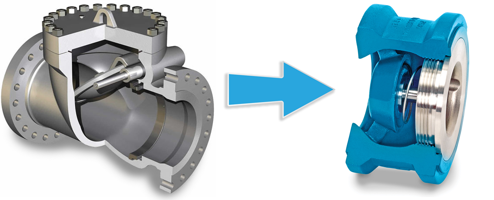
Due to a phenomenon known as column separation, an inordinate amount of head comes back onto the pump when it trips. In this case, a swing check does not close quickly enough to prevent backflow from getting past the valve, and when it closes, it slams shut, and backflow behind the valve hits the disk, the energy has to dissipate somehow, and it does so in the form of water hammer. This occurs because a swing check largely depends on back flow for it to close. A non-slam check valve does not. It utilizes a coiled spring, downstream from the valve disk, that moves the disk toward the seat as soon as the flow velocity slows down. This valve is designed to be closed, just before zero flow is reached, thereby eliminating backflow. With no backflow, the cause of the water hammer disappears.

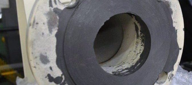
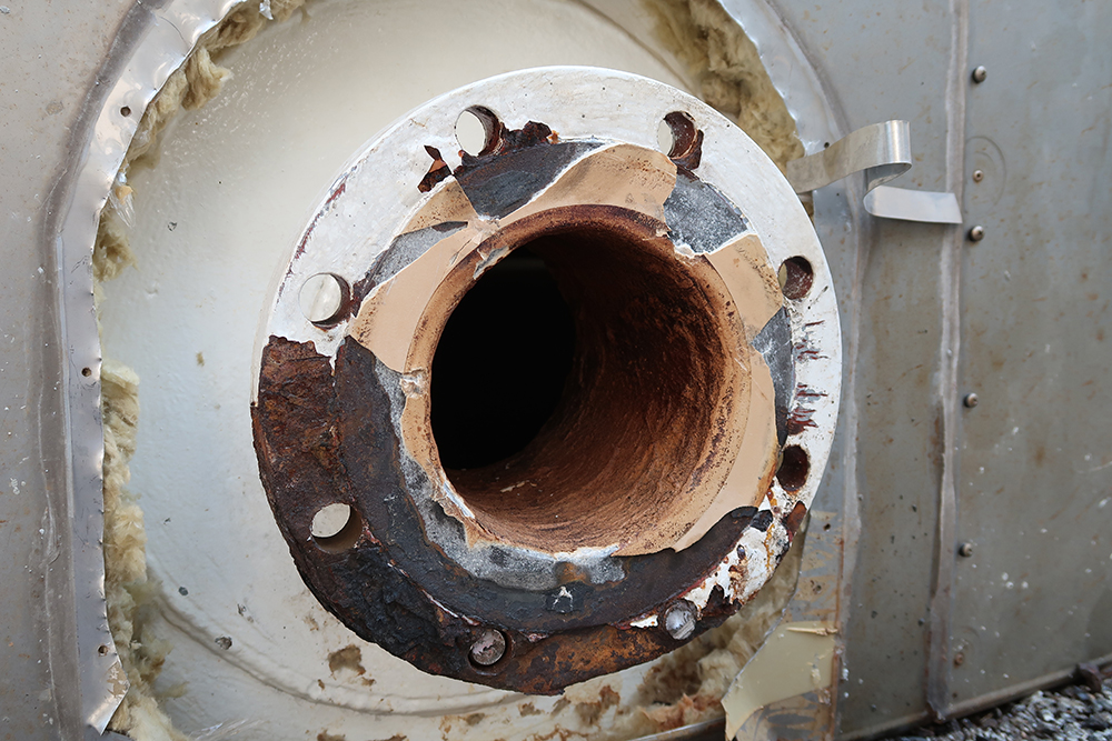
In addition, if a misapplied swing check sees a number of slamming incidents, it is possible for the hinge pin (holding the valve disk in place), to crack, and break off, thereby sending bits of metal downstream, potentially damaging components downstream of the check valve. It is also possible for the entire disk to break off, sending it downstream, leaving nothing but a spool piece.

Designers and maintenance personnel should be aware of situations where backflow and water hammer can be a problem on pump discharge and consider the use of a non-slam check valve in these cases, thereby eliminating the chance that you to may find a disk in your sump!

As the Canadian distributor of DFT® silent check valves, Triangle Fluid Controls Ltd. is proud to represent a company that is known around the world as the valve to use for preventing or eliminating Water Hammer problems – DFT® Check Valves, Serious performance, Superior reliability.

Gasket Joint Safety

June 24, 2019

By: Samantha Harrison, Lab Testing Technician/QA Assistant

Safety First

Being safe on the job includes maintaining and correctly installing gaskets. The number one safety procedure when installing a gasket into a bolted flange joint is to have an assembler who has been qualified in reference to ASME PCC-1. When installing a gasket, make sure proper PPE (personal protective equipment) is worn. This can include safety glasses, hard hats, steel toed shoes/boots, gloves, etc. Proper lockout and tag-out procedures also need to be followed. And it is critical to check that there is no debris, or foreign material on the sealing surface in order to avoid leaking of fluid and gases. Choosing the right gasket is imperative for safety. If a gasket is not the right size or material it can result in leaks, serious damages and ultimately, injury.

Considerations for Bolted Flange Connections:

  • temperature and pressure of the fluid
  • chemical nature of the fluid
  • mechanical loading
  • variations of operating conditions

Different stress variables need to be analyzed when choosing a gasket. This includes minimum seating stress, ideal operating stress, minimum operating stress and maximum operating stress. All these variables need to be understood and taken into consideration. It is always advised to purchase gaskets from a reputable supplier whose priority is to sell quality products and back it up with technical support.

Always make sure that the material of the gasket is compatible with your application. If a gasket is deteriorating it most likely means the material is incompatible with the fluid and temperature. When a gasket deteriorates it can cause leakage which can lead to damages and injuries.

You should never re-use a gasket because it will affect its mechanical properties. As a system expands and contracts, the gasket should move with the piping. If it doesn’t and there isn’t enough load on the gasket you will get a leak which can lead to serious injuries.

When installing a gasket, it is imperative that proper bolting procedure is followed, such as the modified legacy method (star pattern) mentioned in ASME PCC-1. Without proper bolt tightening, leaks can occur resulting in damages and serious injuries. The operating temperature should never be exceeded above the maximum allowable temperature. If the temperature is exceeded it can cause heat cracks and blistering which can inevitably cause leakage.

When disassembling a joint it is important that proper plant procedures are in place. The procedure should include lockout and tag-out to depressurize the system, removal of liquid head from the system. Always loosen the joint away from yourself in case of accidental release.

Here are important questions to ask yourself before disassembling:

  • Is the flange still under pressure?
  • Is there still gas or fluid in the line?
  • What if the piping springs up on release?
  • What if the load swings in my direction?

Knowing when a leak is happening is important to help keep employees safe. Gasket unloading is the most common reason for leaks. This is caused from a joint not able to generate enough seating stress on the gasket material. When gasket seating stress is low it can be from applying the wrong load to the gasket or the inability to transfer the correct load to the gasket from friction that is unaccounted for during tightening. To prevent these issues, a good bolting procedure should be in effect ASME PCC-1.

For other specific applications or general procedures, please contact the TFC applications engineer at tech@trianglefluid.com and read our Bolt Tightening Worksheet here.

Categories